An open source, software based TNC that supports AX.25. Many features of common TNC's are not built-in but we hope to have shed light on not only how AX.25 actually works butto also enable a future developer to implement desired functionality such as bulletin board, APRS, etc.
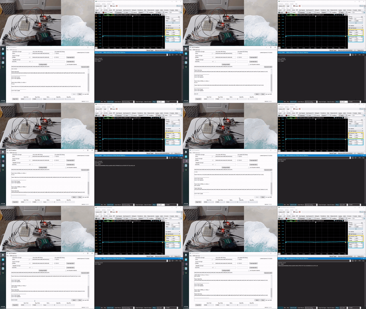
This is a simple demo of one TNC receiving a KISS packet, sending an analog AFSK signal and then another TNC is receiving the analog message! This message is then decoded and output over a serial monitor. The waveform in the top right is a live viewing of this audio signal. It is a short message so not many data points are captured here.
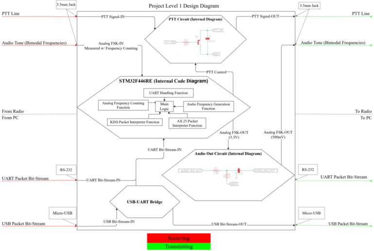
The level 1 diagram gives insight to the basics of how the TNC operates. Hardware required is minimal as the goal was to complete all processing on the ST microcontroller. Notice some hardware is still required for tasks such as PTT line switching, audio output, and a UART bridge to support the microcontroller. Due to the restraints of a shortened semester and COVID-19 some features such as RS-232 and 3.5mm Jack were never fully implemented. Future-Work discuesses the parts of the project that should be developed further when building on the software.
Much of the software has been formatted to allow for queue structures to be implemented as data throughput requirements may need to grow with time. This was done by hosting packet information inside one of two custom datatype we defined as UART_INPUT and PACKET_STRUCT in AX.25.h. As you'll find, most functions simply operate on these global data packets but it wouldn't be very difficult to change the operation to allow input to data pointers.
struct UART_INPUT { // For uart info
int rx_cnt;
int received_byte_cnt;
int flags;
uint8_t input;
bool got_packet;

//HEX Members, includes frame end flags
uint8_t HEX_KISS_PACKET[KISS_SIZE_BYTES];//This is the buffer used to hold hex bits from UART
}UART_packet;

struct PACKET_STRUCT { // For the inbetween stage
//AX.25 Members, does not include frame end flags
bool AX25_PACKET[AX25_PACKET_MAX];//temporary stores bits received from radio, before formatting into AX.25 format

//KISS Members, includes frame end flags
bool KISS_PACKET[KISS_SIZE];

/*
    * 	Packet Pointers:
    * 	Can reference data in either AX.25 packet or KISS packet
    */
bool *address;			//Pointer to address field in global buffer
bool *control;			//Pointer to control field in global buffer
bool *PID; 				//Pointer to PID field in global buffer, only present for I frames
bool *Info;				//Pointer to info field in global buffer
int  Info_Len;			//Length of info field, in bits
bool *FCS;				//Pointer to fcs field in global buffer
bool i_frame_packet;	//Flag to signal if packet is of type i-frames

bool got_packet;
int byte_cnt;


//count for bit stuffed zeros in each field
int stuffed_address;
int stuffed_control;
int stuffed_PID;
int stuffed_Info;
int stuffed_FCS;

int bit_stuffed_zeros;

//CRC
uint16_t crc; 				//crc value after calculating data from PC
int crc_count;
bool check_crc;			//indicates weather validating fcs field or creating fcs field
}global_packet;
The software is heavily implemented inside of interrupt services. The benefit of this is that it allows the end-user to develop their homebrew software to run in parallel while the TNC requirements are still being satisfied. This won't truly be an option until multi-stage ADC sampling (or some other fix) is implemented due to the ADC frequently being serviced currently. Checkout Future-Work point number 1 for more info on this.
The software is broken into many include files. This keeps the code from being very dense and hopefully portrays our thought process when structuring the functionality. This is a brief summary of the purpose for each file.
- FreqIO.h
- This file defines methods for directly controller hardware. Setting hardware mode, timer reload settings, DAC control, etc. are setup here.
- This is the lowest level in the hardware control.
- AX.25.h
- This file defines methods for handling data processing of AX.25. These methods do not directly control hardware.
- interrupt_services.h
- This file defines methods for handling interrupt callbacks. Interrupt corresponding macro definitions are found here.
- sine.h
- This file defines LUTs for the controller. A sine wave LUT is saved and a arcsin LUT are saved.
- debug.h
- This file defines methods for debugging. These methods mostly consist of print statements.
- To enable debug printing, set debug_printing true
- To force controller into repeat broadcastmode, set BROADCASTR true
- More debug functionality could probably be instrumented in the code but this is a decent start
- Documentation: Simply holds some important information we found when trying to unravel the mess of AX.25. This protocol has many technical definitions but you'll find that the HAM community unfortunately has not stayed very true to this standard. This particular area could use more work but we tried to to do a good job at notating our work and assumptions from reverse engineering some hardware we worked with at the time. Also checkout our final paper for details.
- Schematic: Not much here except our LTSpice schematic for the PTT circuit but with more hardware realiztions of future projects, this should fill up easily.
- Software: Being a software TNC, this folder has quite a bit from our experimenting. You'll find a single CUBE project hosted called MCUTNC, this is our final software version. It has all the bells and whistles implemented that we were able to come up with. On the side of this you'll see the Code Playground. This is basically where we did our prototyping with the different hardware functionalities of the STM controller. This was left in just incase any further protyping may want to be completed. 🎅 🍑
- Limited voltage range input
- This is probably the biggest issue with our software that prevents this from being a fully functional TNC. As of now the device will only properly read a signal with a ptp of 3.3V, 1.65V centered.
- The fix is relatively straightforward, the software should become a little smarter and add a couple more modes of receiving. There are likely other methods but this is just a recomendation from the original developer. The definition of Low, Medium, and High polling rate are not strict here but the idea is to only sample as much as really needed so the controller can services other parts of software if needed.
- (Stage-1) Low Rate Polling Mode : This will be the default receiving mode for the TNC when no signals are detected and establishes the baseline noise, etc. This should be set to conserve power and only exit this mode when some voltages are coming in.
- (Stage-2) Very High Rate Polling Mode : This will be stage 2 of the analog receiving logic. The callback function should do minimal to achieve as high of sample rate as possible. During this stage, the controller will be establishing the characteristics of the wave, specifically the amplitude of incoming wave, and DC offset. AX.25 packets are preceeded by a string of 0 bits so this would be a great time to lock this info in, but make sure to leave time for the clock to sync in stage 3. After these are done, ensure to update the asin LUT. The gen_asin() function will be a good place to do this.
- (Stage-3) RX Logic, Medium Rate Polling Mode : This is essentially what we have already implemented and will actually decode the message now that the characteristics of the incoming signal have been established. Its worth mentioning we focused on optimizing the callback function to be as minimal as possible to keep poll rates as high as possible. Higher poll rates tends to lend to a more accurate frequency representation of the incoming signal.
- RS-232 Port
- It is normal for HAM radio users to plug a TNC via an RS-232 port into a computer. This wouldn't take too much effort to implement as this is mostly a hardware issue.
- 3.5mm Jack
- Again, another creature comfort implementation. Since our project never left the bread board is wasn't exactly neccessary for us to put this in. It is worth mentioning that the output from the controller should be as high of resolution as possible. So this means you should keep the output signal at 3.3V ptp and simply use extrernal hardware to lower the voltage before inputing into the radio.
- Push-To-Talk Circuit (PTT)
- Luckily, this is actually already designed and tested for you but due to our project never connecting to a radio, we don't have much documentation of physical testing. Take a look at the PTT Circuit Information for the details on this.
Follow this guide to install the STM32Cube IDE. This is an IDE created by ST for their boards/processors. The STM32Cube IDE is based on ECLIPSE add-ons and GNU C/C++ toolchain and GDB debugger.
This guide will also step you through the process of creating a simple code to blink the onboard LD2. This project is based the NUCLEO-F446RE. Porting will need to be done for other MCUs!
Guide Created by Digi-Key: https://www.digikey.com/en/maker/projects/getting-started-with-stm32-introduction-to-stm32cubeide/6a6c60a670c447abb90fd0fd78008697
- This repo is a slimmed version of our original GitHub repo. If anything seems to be missing or is not clear, visit: https://github.com/MrLordLeon/TNCMCU
- Keep in mind the other repo was our raw data base when working on the project for a senior design capstone project and has a lot of unecessary or intermediate information
- Hopefully this is a good tool for learning about AX.25, KISS, and how to use this protocol. Be sure to checkout some of the appendices in the out design paper as this has detailed information on subsystems as well.
| Developer | GitHub | |
|---|---|---|
| David Cain | d.cain2740@gmail.com | https://github.com/monkeyboyfr3sh |
| Kobe Keopraseuth | kobekeo@gmail.com | https://github.com/kobekeo24 |
| Kaleb Leon | kalebleon@aol.com | https://github.com/MrLordLeon |

