Zooids: Building Blocks for Swarm User Interfaces \ Extended Material
 This paper introduces swarm user interfaces, a new class of human-computer interfaces comprised of many autonomous
robots that handle both display and interaction. We describe the design of Zooids, an open-source open-hardware platform
for developing tabletop swarm interfaces. The platform consists of a collection of custom-designed wheeled micro
robots each 2.6 cm in diameter, a radio base-station, a highspeed DLP structured light projector for optical tracking, and
a software framework for application development and control. We illustrate the potential of tabletop swarm user interfaces
through a set of application scenarios developed with Zooids, and discuss general design considerations unique to swarm user interfaces.
Hardware
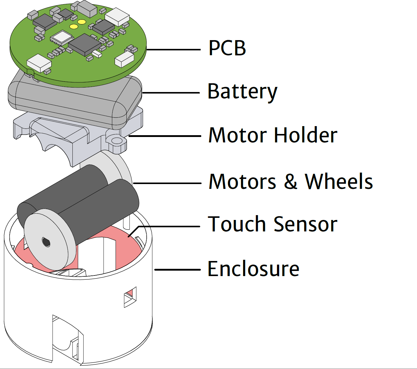
Zooids are small custom-made robots as shown above; their dimensions are 26 mm in diameter, 21 mm in height and they weight about 12 g. Each robot is powered by a 100 mAh LiPo battery and uses motor driven wheels. It contains a flexible elctrode for capacitive touch sensing. It communicates with the main computer through a NRF24L01+ chip.
Tracking
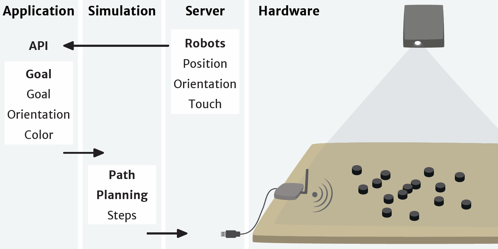
Our system uses a projector-based tracking system for robot position tracking as shown below. Using a high frame rate (3000Hz) projector (DLP LightCrafter) from Texas Instruments Inc., a sequence of gray-coded patterns are projected onto a flat surface. Then, the photodiodes on the robot independently decodes into a location within the projected area. The instruction for setting up this projector-based tracking system is included in the repository.
Software
The communication structure consists of four main layers from highest to lowest level: Application, Simulation, Server, and Hardware.
At the application level, the desired positions of the robots are computed. These desired positions are transmitted to the simulation layer through a network socket. The application programmer can choose between two control strategies: Proportional-Integral-Derivative (PID) position control or Hybrid Reciprocal Velocity Obstacles (HRVO) combined with PID (these options are explained in the next paragraphs). Based on the chosen control strategy, the simulation layer computes the goal positions of the robots, either final positions for PID or intermediate points for HRVO, and sends them to the server. Finally, the server layer dispatches commands to the individual zooids, while at the same time monitoring their status and position.
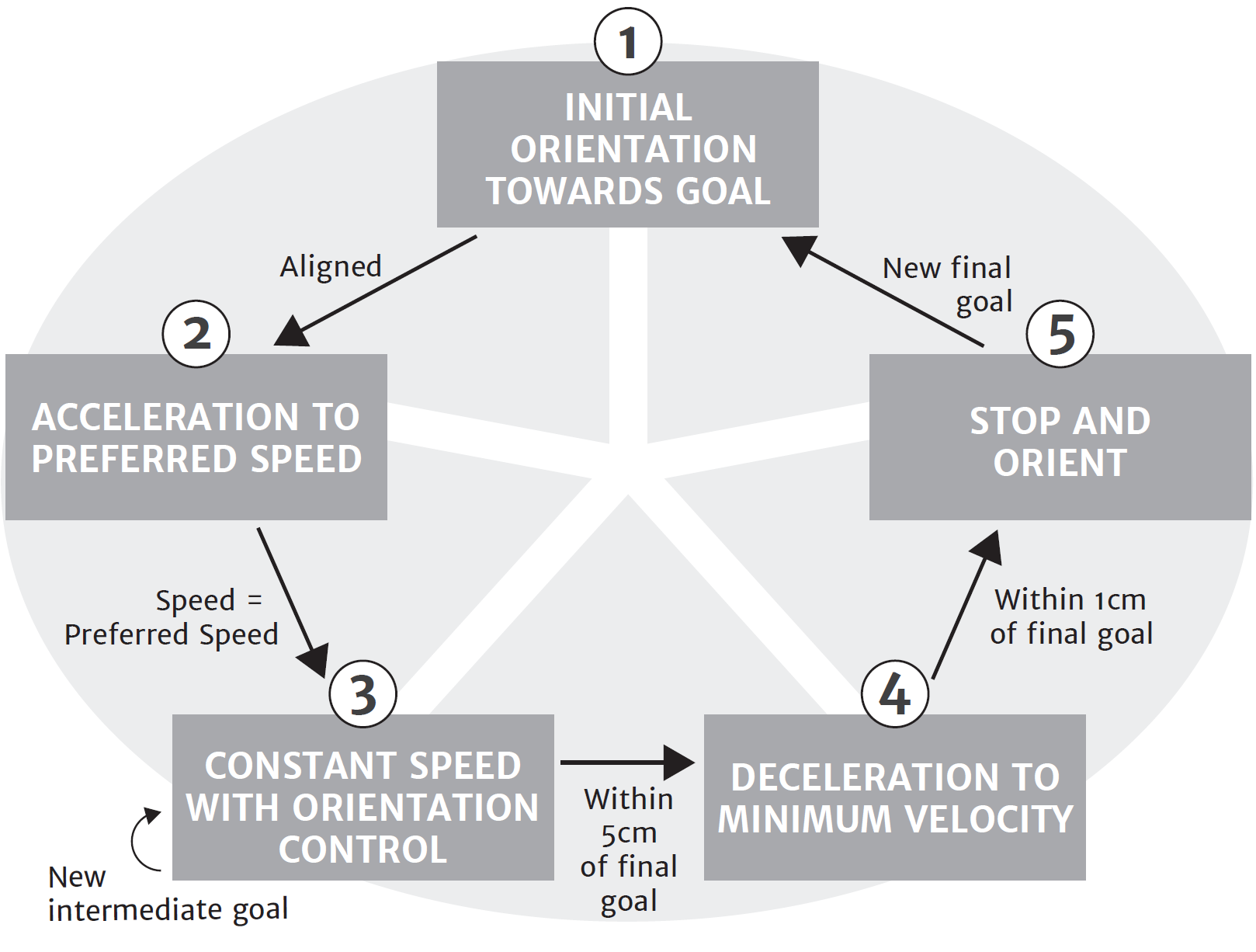
Each robot independently controls its motion through a PID controller based on the state machine shown below. Given a final goal, the robot initially turns itself in the right direction and, once aligned, accelerates to its user-defined preferred speed. When it reaches the speed, it maintains it with a PID control on the orientation to ensure its direction towards the final goal. When a new incremental goal is given, it will still move at same speed but the PID control on orientation will direct the robot towards the new intermediate goal. When the robot arrives within 5 cm of the final goal, it slows down to its minimum velocity and once within 1 cm of the final goal, it stops and orients itself as commanded by the application programmer. To enable smooth transitions between the incremental goal positions, robots are given their next position at 60 Hz.
Acknowledgments
This is a joint work between the Shape Lab at Stanford University (USA) and the Aviz team at Inria (France). It was partially funded by the Région Ile de France, DIM ISC-PIF. We would also like to thank Alexa Siu, Shenli Yuan, Ernesto Ramirez and Pham Minh Hieu for investing so much time and efforts in making this work possible.
This work is licensed under a Creative Commons Attribution-ShareAlike 4.0 International License.


