
This is an Autodesk Fusion 360 script that's used for generating surfaces from images.
This surface was created from a small height map of a crater on Earth's moon. The first image is the mesh created from the script.The second is the T-Spline surface created from the mesh.


This is a penny that was milled out of a 4"x4" block of 6061 Aluminum. The surface was created from a height map of a penny. The mesh was then converted to a T-Spline then merged onto a cube. That model was brought into the CAM environment where the various milling operations were defined. Finally, it was milled on a Haas CNC vertical milling machine.


Copy the "Fusion360Image2Surface" folder into your Fusion 360 "My Scripts" folder. You may find this folder using the following steps:
- Start Fusion 360 and then select the File -> "Scripts and Add-Ins..." menu item
- The Scripts and Add-Ins dialog will appear and display the "My Scripts" and "Sample Scripts" folders
- Select one of the "My Scripts" files and then click on the "+" Details icon near the bottom of the dialog.
- If there are no files in the "My Scripts" folder then create a default one by clicking the Create button, select JavaScript, and then OK.
- With a user script selected and the "Details" section expanded, look at the Full Path value. This contains the location of the user scripts folder.
- Copy this script's folder into that location. For example, on my Mac the folder is located in: /Users/USERNAME/Library/Application Support/Autodesk/Autodesk Fusion 360/API/Scripts And on Windows: C:\users\USERNAME\AppData\Roaming\Autodesk\Autodesk Fusion 360\API\Scripts
- Now add the script to the lists of "My Scripts"
- Click the "+" icon next to the "my Scripts" item
- The "Add new script" dialog should appear.
- Locate the ForceEffectImport.js file in the folder you copied, select it, and click Open. The script should now be installed and ready to be run.
The script should be ready to run.
- Enter the Model environment
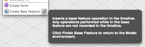
- If not in direct modeling mode, create a Base Feature that will hold the surface mesh
-
Select Create->Create Base Feature

- Run the "Image2Surface" script from the Script Manager

- A file dialog will be displayed.
- Select an image file to convert to a surface and click OK.
- Note, because of limitations in Fusion on the size of meshes, I highly recommend using only very small images. For example, the moon image used to generate the above surface is only 50x50 pixels. If you have an image that's large then create a smaller version of it then import that.
- The settings dialog will be shown. Adjust your preferences:

- Style : Select one of the following styles to generate
- "Mesh Body" : mesh that can be converted to a T-Spline
- "Sketch Points" : sketch containing points for each pixel
- "Sketch Lines" : sketch containing lines simulating a mesh (warning SLOW)
- Mesh stepover length : The length of each face of the mesh
- Max surface height : The maximum height the normalized image values are mapped to.
- Invert image : Invert the height values of the image. White is low and black is high.
- Export format : Select one of the following
- "OBJ" : a Wavefront OBJ file containing the mesh (quad faces)
- "STL" : a STereoLithography file containing the mesh (triangle faces only)
- Click OK to generate the surface
- Note, if an OBJ or STL file with the same name as the image file already exists you will be prompted to overwrite it.
Once the mesh or sketch is created it will be added to the drawing. You might have to "fit" the view to see it.
If you have created a mesh then it's useful to convert it to a T-Spline or BRep for further modification. Note, Fusion has a limitation on the size of the mesh that can be converted. It's around 10K faces.
-
Mesh to T-Spline
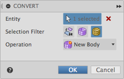
- Enter the Sculpt environment
- Select the Modify->Convert toolbar item
- Follow the steps in the dialog to convert the mesh to a T-Spline
-
Mesh to BRep
- Enter the Model or Patch environment
- Select the mesh
- Select the Modify->Mesh->Mesh to BRep toolbar item

Note that the default settings "Mesh Body" style and "OBJ" export format are required for a usable mesh to be used in Fusion 360. The other two styles are good for experimenting but don't create a mesh. And the STL format only supports triangular faces, which can be used to create a mesh in Fusion, but the mesh can't be converted to a T-Spline. Note, you can use the OBJ or STL file generated in another application such as Autodesk Meshmixer. For example, to decimate the mesh (simplify) and then load that into Fusion 360.
Here's the heightmap image of the moon's surface that was used to generate the mesh and t-spline shown at the top of the page.

And here's the t-spline in the CAM environment being used to create toolpaths for milling:

More examples posted on my Fusion 360 project gallery.
- 2016.02 : Fusion 360 has a 10K limitation on mesh size when converting to a T-Spline. Any larger and it fails.