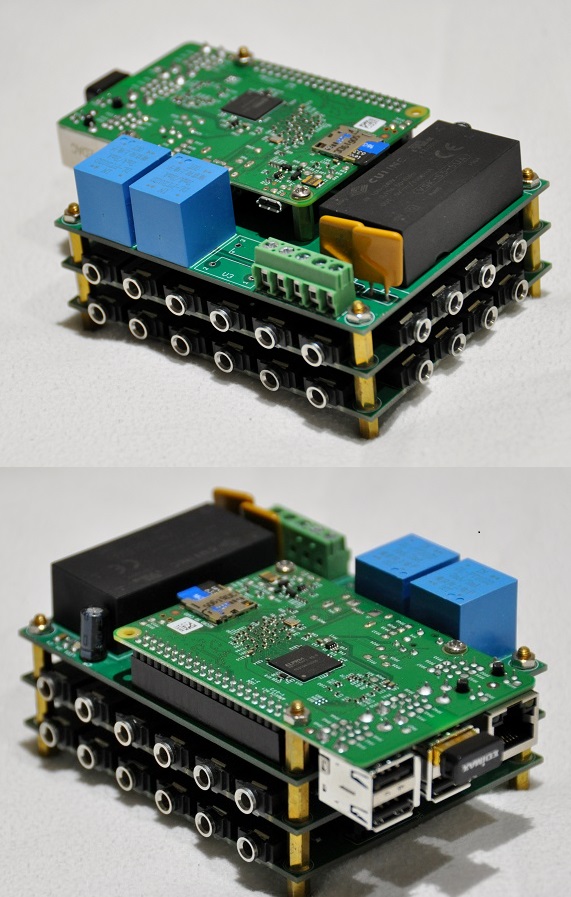
PiPowerMeter is an energy usage monitor based on the Cirrus Logic CS5463/5490 energy IC's (http://www.cirrus.com/en/products/pro/detail/P1092.html) and a Raspberry Pi. It consists of two custom designed stacking pcb's. The control board houses the power supply, energy IC, voltage sensors and supporting electronics. The input board houses 16 multiplexed current input channels that allow monitoring up to 16 different circuits via standard clamp-on ct's. A single control board supports up to 8 stacked input boards for a total monitoring capacity of up to 128 circuits. The system is controlled by a nodejs based program running on the Raspberry Pi and includes a self contained web based monitoring portal. Energy data are stored locally on the Raspberry Pi in a sqlite database making the system 100% stand-alone with no requirement for additional hardware or external servers.
- 100% stand alone system with no reliance on external hardware or servers
- Ability to monitor up to 128 circuits via round-robin sampling
- Uses simple off the shelf clamp-on current sensors
- Highly accurate measurement of voltage, current, power usage and power factor based on CS5463/CS5490 energy IC
- Raspberry Pi based control system
- All data stored locally in sqlite database
- Web based monitoring portal for viewing energy usage and configuration
- Ability to receive text alerts for overloads or other events.
-
The Raspberry Pi mounts directly to the 40-pin header on the control board and is powered from the control board's universal power supply. Do not attempt to power the Raspberry Pi via its micro usb port or it may be damaged.
-
The control board requires a direct connection to the AC power source that is being monitored. This AC connection provides both the voltage reference for the energy calculations as well as the power source for the Raspberry Pi and supporting electronics. The AC power source is connected via 5 pin terminal connector shown here and supports 100-240VAC and 50/60Hz.
- For US 120/240V split phase connect Ground, Neutral, AC1 and AC2.
- For 240V single phase connect Ground, Neutral and AC1.
- For 3 phase connect Ground, Neutral, AC1, AC2 and AC3.
-
Current sensors are connected to the input board via standard 3.5mm (1/8") audio plugs. They must be current-type sensors without built-in sense resistors and must produce a full scale output of less than 50mA. YHDC produces a full line of split-core current sensors that are easy to use, inexpensive and readily available online. Popular models include:
-
Connect the current sensors so that the current polarity reads correctly, (+) for circuits that consume energy and (-) for circuits that produce energy. Connecting a sensor backwards will not harm anything so if you're not sure which way it should face just pick a direction and then reverse it if the readings are opposite of what you expect.
- Current sensors measure the sum of the current passing through them so they should normally be connected to a single conductor. If connected to a multi-conductor cable, the current flowing in the line and neutral conductors will cancel each other and the sensor will read zero current.
- YHDC sensors connected to line conductors should be oriented so that the printing on the face of the sensor faces toward the source (there's also an arrow on most sensors that should point toward the source). If the sensor is connected to the neutral the direction should be reversed.
-
Once the sensors are installed you'll need to configure the software to enable them. This is done in the configuration page by adding a new circuit for each sensor and setting the sensor type, board, circuit and voltage reference.
- There are several preconfigured types for common YHDC sensors and you can add additional types under the configuration tab. When creating new sensor types set the scale value to 0.05 * the turns ratio of the sensor. (YHDC SCT-013 has a turns ratio of 2000:1 so scale factor is 0.05*2000=100)
- Board should be set to the id of the current board that the sensor is plugged into (0-7).
- Channel should be set to the id that the sensor is plugged into (0-15).
- Set Voltage to the voltage reference for the circuit. If you aren't sure you can take a look at the current and voltage waveforms on the circuit page and experiment until you find the voltage reference that most closely matches the phase of the current waveform.
- SampleTime sets the amount of time in seconds that the input current and voltage are sampled for each calculation. Decreasing the SampleTime allows faster sampling but may adversly affect the accuracy of the calculations. Valid values are between 0.05 and 60 seconds.
- Incorrect software settings won't cause any damage so you can experiment until you get them right.
- Any of the full size Raspberry Pi models with the 40 pin header are supported including: V1 A+, V1 B+, V2, V3 B, V3 B+ and V4 B. The additional memory and computing power of the V2/V3/V4 models is recommended.
- Start with latest Raspbian image from https://www.raspberrypi.org/software/operating-systems/
- (verified with Raspberry PI OS Lite 2021-03-04)
- It's recommended that you use the Lite version because it's smaller and installs faster but you can use either.
- login to Pi with Putty or other ssh client
- the latest versions of Raspbian have ssh disabled. You can enable ssh via raspi-config or just create an empty file named 'ssh' in the boot partition of the sd card.
- Install the PiPowerMeter software by running the following command (you must install with root privileges such as the built-in pi account):
- run 'sudo raspi-config'
- set locale and timezone under Localisation options
- expand filesystem under Advanced options
- change user password (optional)
- reboot when prompted after exiting raspi-config
- Open your browser to http://<Your Raspberry Pi's IP Address>:3000