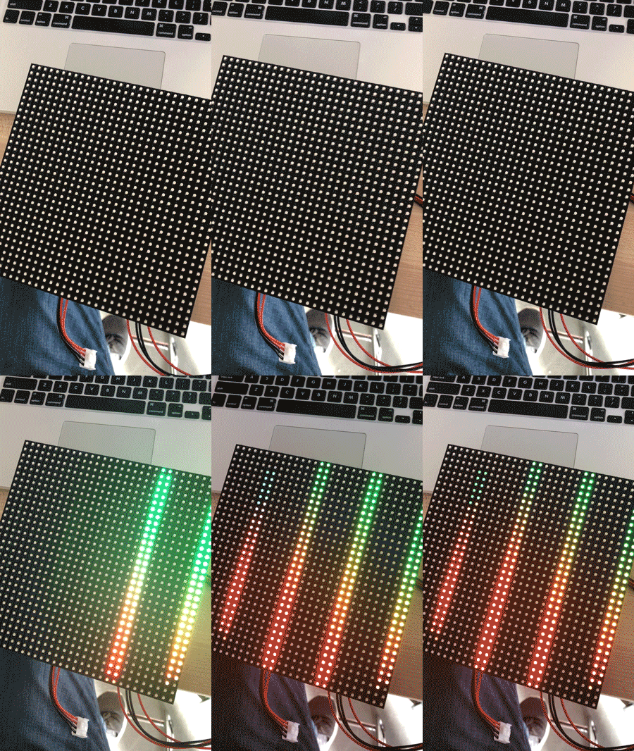
Original idea and prototype
Check-in 11/8
Final deliverable 12/4
Project Idea
We are using an LED panel connected to a webcam to visualize information through color.
Originally, we planned for possible features to include:
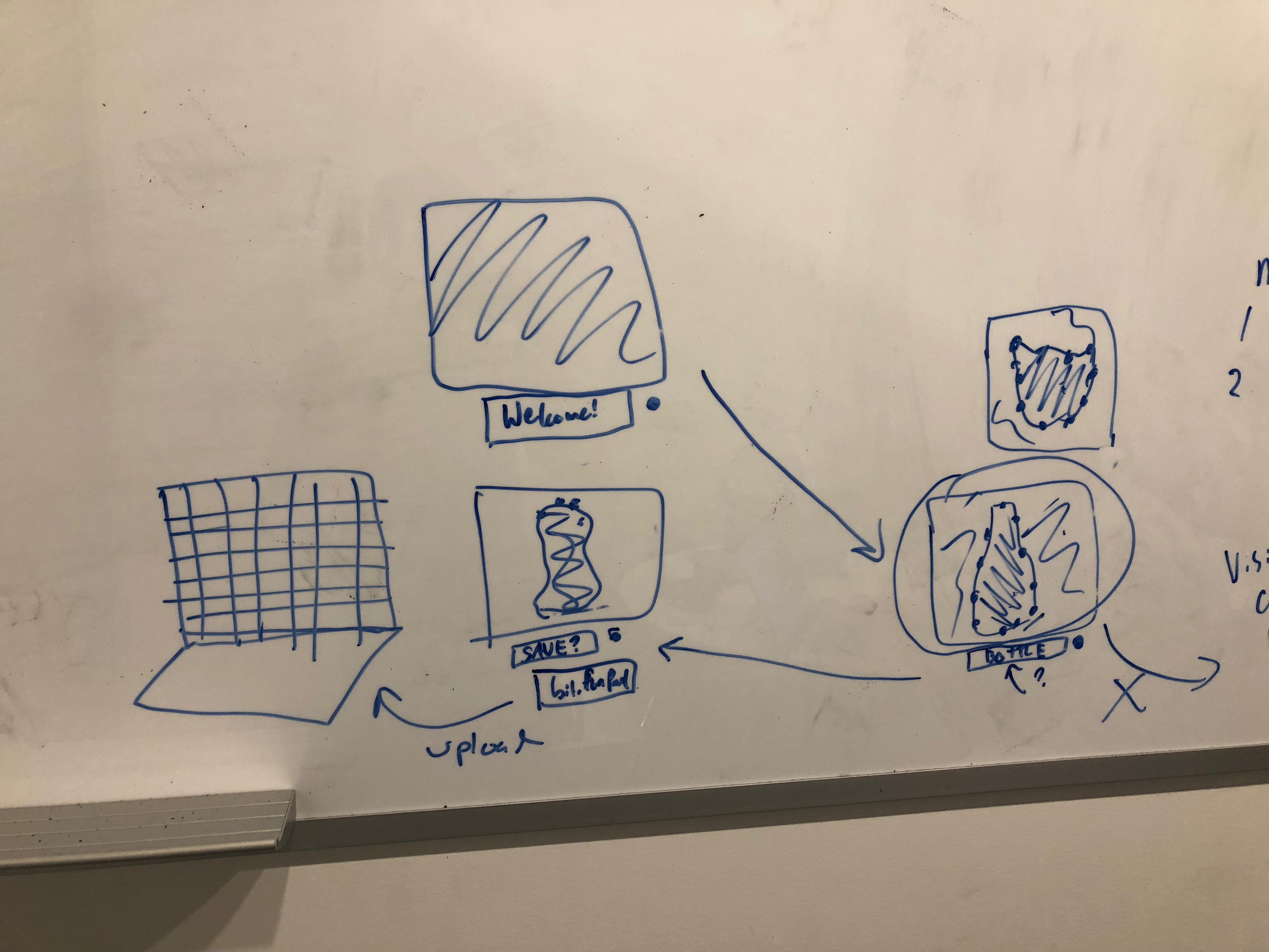
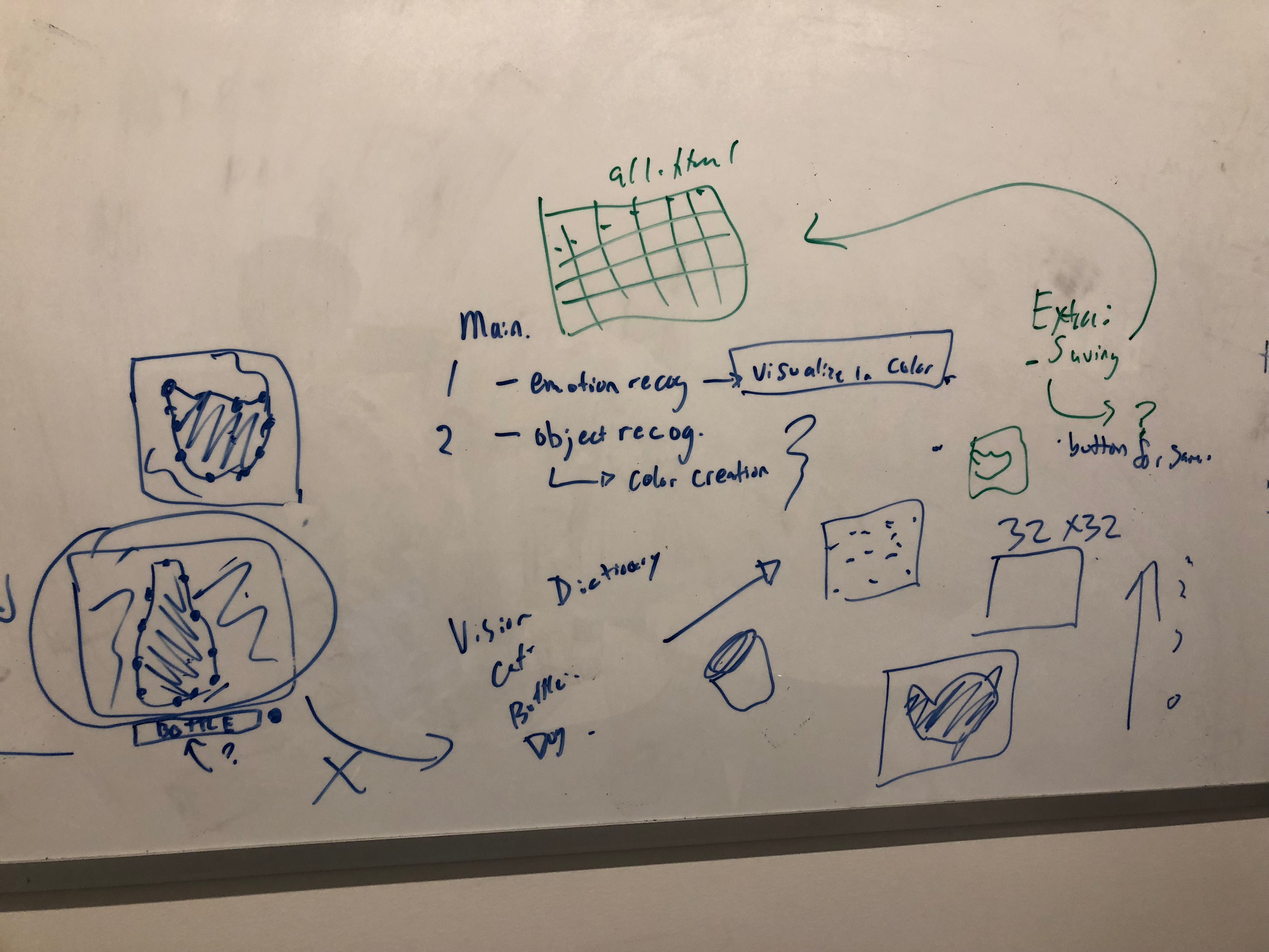
- Live conversion of webcam image to 32x32 LED display
- Recognize emotion of person's face and visualize on LED panel using color
- Object recognition: use computer vision to recognize object and display cartoon version on LED panel
- Image capture: allow user to press button and save 32x32 image to a web page
- LCD panel displaying text that describes the image below the LED panel
Ultimately, our design focuses on visualizing the user's emotion on the LED panel based on an image captured from a webcam.
Who Is This Device For? This device can be used as entertainment! It can be placed on the wall in a lobby and users can walk up to it, express an emotion in front of the camera. This emotion will then be translated and visualized on the LED 32x32 panel. We discovered while building this device that it's fun to make silly faces and see them displayed back as emoji on the LED panel. If you're feeling grumpy (as we were toward the end of this project) this device will brighten your day.
Team
Devon Bain (dwb264)
Christopher Caulfield (ctc98)
Rough Form
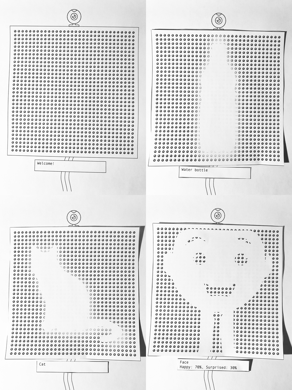
Paper prototype:
Whiteboard sketches:
Expected Parts
- 32x32 LED Panel
- LED Panel Shield
- Raspberry Pi
- Arduino
- Webcam
- LCD panel
- Button (maybe)
Interaction Plan
Original plan:
The webcam will be attached to a wall at face height. The user can stand in front of it or hold an object in front of it. The LED panel will automatically change based on the camera image. There will be a button the user can press to save the image. The LCD will display a URL the user can visit to see their 32x32 image.
Final implementation:
The LED, webcam, button, and arduino are all semi-enclosed in a clear acrylic stand. The stand can be placed on a table, and the user can sit and press the button while looking into the webcam. The LED panel then displays an animation and emoji representation of the user's emotional state.
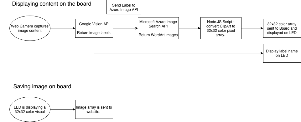
Interaction Diagram
Interactive Device
Learning Experience
Panel shield soldering
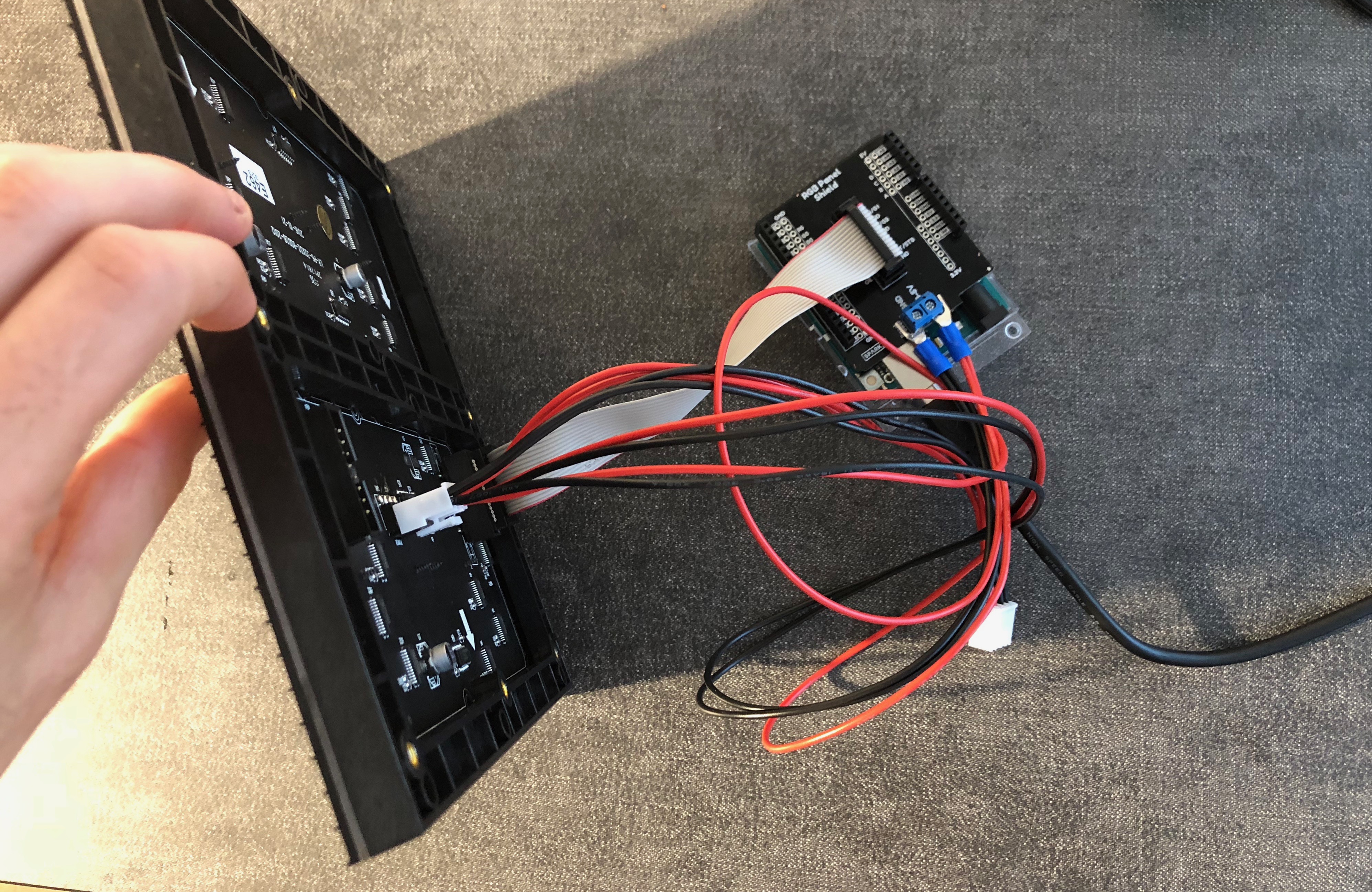
To make our lives easier, we bought a panel shield accessory that allows us to directly plug the LED panel into the Arduino. It required soldering about 30-40 different connections, and one piece was soldered backwards. It had to be de-soldered and flipped around in order to connect the panel correctly.
Magic smoke
When we first tried to power up the panel and Arduino, we mistakenly used a 9V adapter instead of the recommended 3-5V. This, possibly in combination with the backwards component, caused the panel to start smoking. The panel was partially burnt out as a result, and we have ordered another from SparkFun that should arrive next week.
Completed Work
- Wrote code to obtain small images from image search API
- Figured out correct setup for connecting LED panel and Arduino
- Wrote script to download images from an array of urls and resize to 32x32
Next Steps
- Combine image search, Google Vision and image-resizing scripts to resize images retrieved from the API
- Convert 32x32 image into an array of RGB values which can be sent to the LED panel
- Incorporate webcam and button into device to use webcam as source for the initial photo
- Incoporate LCD panel into device to display instructions/feedback to the user
Hardware Constraints
After completing the backend logic of converting an image onto a 32x32 LED display. We discovered displaying the image was much harder than expected! First the Arduino Uno has a limited amound of SRAM (2k bytes). The 32x32 LED takes up 1.6k bytes leaving .4 remaining for all other SRAM processing. This makes it difficult to manage the different communications going in and out of the Ardunio such as the LED and Serial reader/writer. Secondly, the most popular LED display library on Github provided limited documentation about how to display a custom 32x32 image on the LED display. Finally, writing color pixels to the serial was also difficult, we were only successful at reading in single 'Chars'. Initially we wanted to display strings of RGB values for each pixel.
Because of these issues with the LED display, SRAM, and Searial reader we focused on how to display information on the LED given a single Char value. Displaying a image on the LED was no longer feasible, but display emotion was. We decided to build out this functionality and enhance it as our final project.
LED Functionality
Our project demonstrates many features of the LED matrix library. We use matrix.drawCircle to animate circles of different sizes and colors, creating a "thinking" effect. We also use the text and line drawing functions to display the initial instructions on the panel. Finally, we display images by copying data from PROGMEM to the matrix buffer.
Images - how?
Displaying images on the LED was very difficult. We found a reliable solution which involved several steps. First, we downloaded images of the emoji we wanted to display. We then wrote a python script to resize the images to 32x32 and output 1024 matrix.drawPixel commands to color each pixel of the LED. Then, we ran those 1024 matrix.drawPixels on the arduino and used matrix.dumpMatrix to convert the matrix display into a .h file, which can be quickly loaded from PROGMEM.
We experimented with different emoji sets and found that Microsoft emoji displayed better than Apple emoji at the 32x32 resolution. We also found that matrix.Color333 with rgb values from 0-7 was sufficient for clearly displaying the images; we did not need the full 0-255 rgb color range.
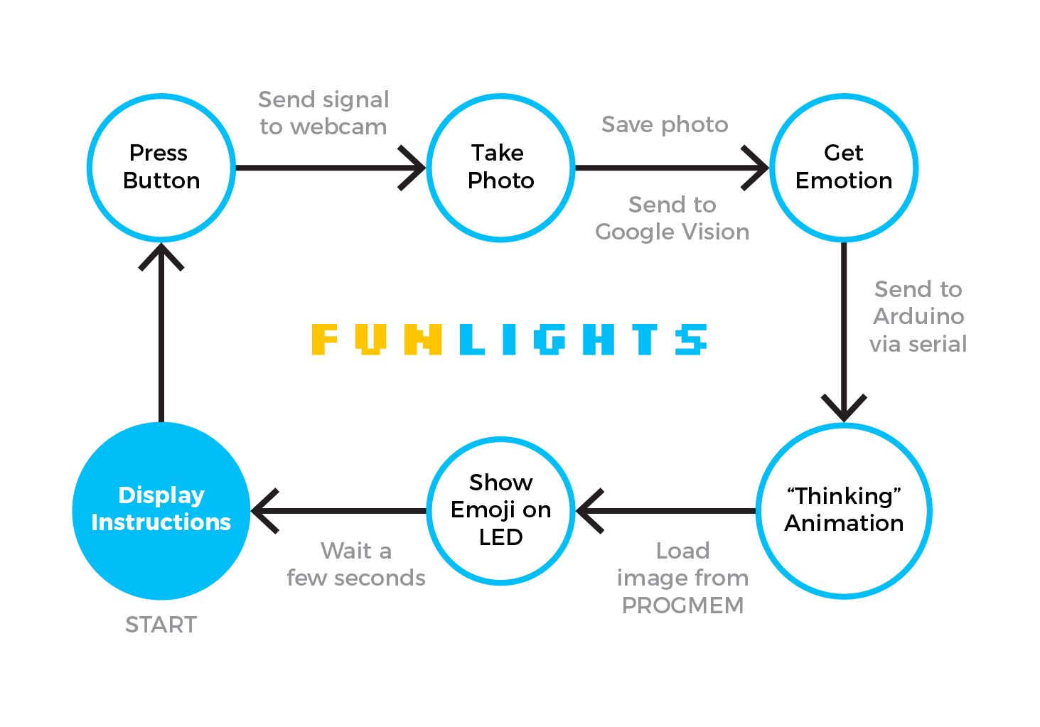
State Diagram - revised
Final Code
All final project code can be viewed in the Master branch.
Final Video
Final video can be found here: https://www.youtube.com/watch?v=Z7KM9nJAe3Y
