Visual inspection of civil infrastructure is customarily used to identify and evaluate faults such as cracks, corrosion, or deformation. However, current procedures followed by human inspectors demand long inspection times to cover large and difficult to access bridges, and rely strongly on the inspector’s subjective or empirical knowledge. To address these limitations, a new vision-based visual inspection technique is proposed by automatically processing and analyzing a large volume of collected images from unspecified locations using computer vision algorithm. By evaluating images from many different angles and utilizing knowledge of a fault’s typical appearance and characteristics, the proposed technique can successfully detect faults on a structure.
Chul Min Yeum and Shirley J Dyke. “Vision-Based Automated Crack Detection for Bridge Inspection.” Computer-Aided Civil and Infrastructure Engineering 30, no. 10 (2015): 759–770.[Web].
Chul Min Yeum and Shirley J. Dyke. “Vision-based Automated Visual Inspection of Large-scale Bridges”. Sixth World Conference on Structural Control and Monitoring, July, 2014. [Paper],[PPT].
- All source code are released in this repository.
- You can download original images and results from this link [Link].
- If you use the code and images for your publication, please cite my paper(s).
I acknowledge support from National Science Foundation under Grant No. NSF-CNS-1035748. I would like to thank Dr. Robert J. Connor and Matt Hebdon at Purdue for providing the test structure and invaluable comments for this study.
Display the outcomes in the paper
- Clone (or download) the source code in github into a directory of your choice.
- Download and unzip images and output data from the above link and allocate them in the same directory. In the directory, you will have folders of "code","img" and "post". You can also manually setup the path of "img" in
Parameters.m. - Run
RunOutput.m.
Train your own classifier using your images
- Clone (or download) the source code in github into a directory of your choice.
- Manually annotate your object-of-interest using
RunLabeling.m. - Run
RunTrainClassifier.mandRunTest.m, consecutively. However, you have to modify and update parameters inParameters.m, applicable to your own application. - I would recommend that you first understand the flow of the code using the images in the paper.
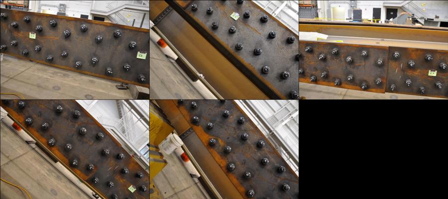
Five images collected from the same structure were used for training.
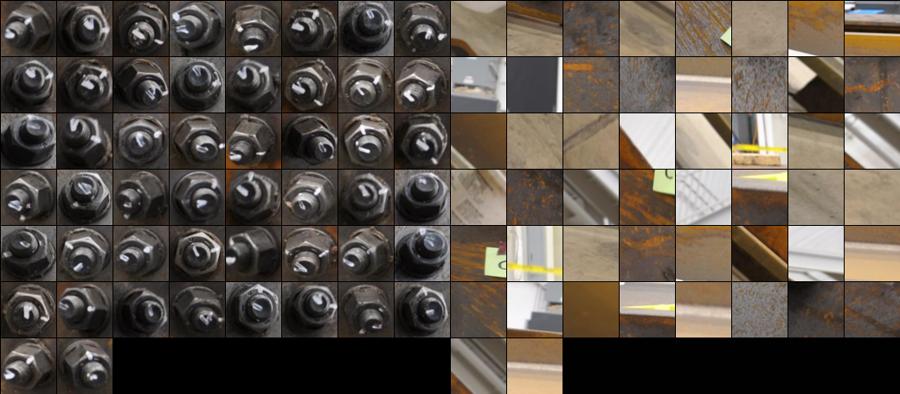
Positive (right) and negative (left) patches were annotated and extracted from the training images.
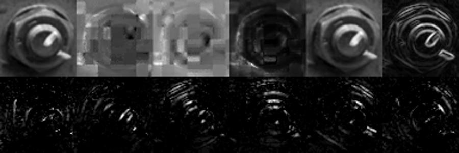
A total of 11 channel images are used to extract features, including U and V components in LUV, H and S components in HSV, gradient, and histogram of gradient with 6 orientations (0°, 30°, 60°, 90°, 120°, 150°).
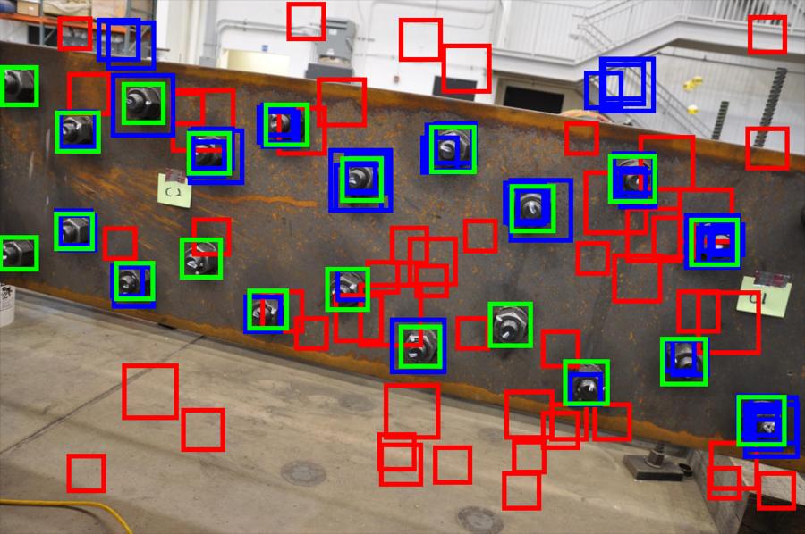
Green,blue, and red boxes indicate ground-truth bolt patches, detected positive patches, and detected negative patches, respectively.
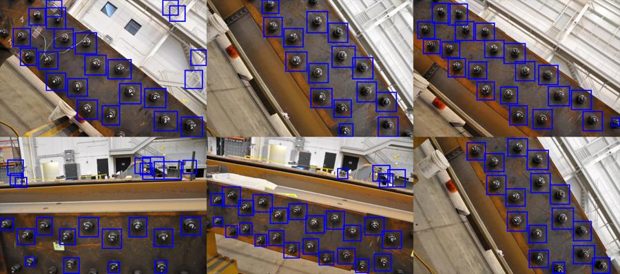
All 67 images are used for testing.
Blue boxes indicate detected positive patches.
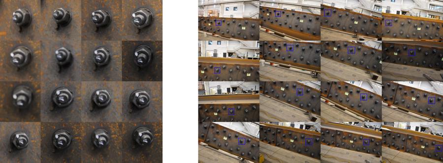
All 68 bolts are successfully grouped. The bolt patches on the right indicate same bolt, extracted from test images on the left.
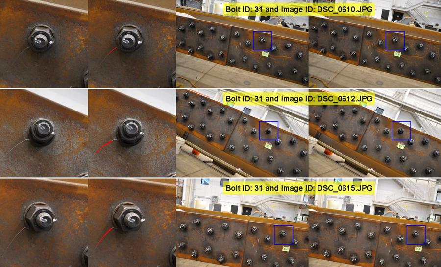
Crack detection on the Bolt (a): The red line is the detected crack.
Crack detection on the Bolt (b): The red line is the detected crack

