
- Dave Giller KI3V - Programmer and designer
- Frank IZ8DWF - Testing methodology and initial test routines
- Adrian Black - Testing, initial concept and QA
This project was born out of a broken TRS-80 Model 3 that I was working on. I could not tell if the system was even "executing code," so I used an early version of this ROM to help diagnose the problem.
Please know that the main goal of this ROM is to test the functionality of the video RAM (VRAM) and the dynamic RAM (DRAM, system memory.) It does not test any other component unrelated to those two subsystems. If a TRS-80 has good VRAM and DRAM, it should boot into basic where you can then run further tests.
You should familiarize yourself with the system schematics and design of the TRS-80 before using this ROM since problems in other areas of the system can sometimes manifest themselves of a RAM problem.
Videos:
In addition, most (all?) RAM tests contained inside diagnostic ROMs on various systems use a very rudimentary RAM test that are inadequate to detect subtle RAM problems. While the test in this ROM isn't the end-all, be-all of RAM tests, we feel it is better than the typical simple bit pattern tests used elsewhere. The RAM test implemented here is a "march" test, which we have found to be much more reliable at detecting a variety of different RAM fault modes.
- No working RAM is needed. This ROM can work on a machine with faults in both VRAM and DRAM. For more information, see this explanation of the techniques used to operate in the absence of working RAM.
- Keep in mind however, that other faults, such as address line problems, can keep this (or any) ROM from running properly.
- One ROM image for both Model 1 and 3 and all DRAM sizes
- Audio feedback via the cassette port, so you can tell what's happening even if you have no video display
- Auto detection of VRAM type (The Model 1 comes with 7-bit VRAM)
- Auto detection of bank size (4k or 16k)
- A machine with 4K bank size cannot have RAM at 12K ($7000). If the ROM tests that region and finds all bits bad, it assumes this is a 4K machine.
- Officially, a machine with a 4K bank can only have 4K total, so this ROM does not test beyond the first bank in that case.
- Testing up to 48k of DRAM, looping continually
- Fits within 2K so the ROM can be used on a Level 1 machine
- Porting the ROM to other TRS-80 systems like the Model 2 and Model 4
- Porting the diagnostic routines to other Z80 systems
- More comprehensive documentation
- Makes a beep from the cassette port (so you can know the system is executing the ROM.)
- Set the system to 64 column mode.
- Tests the video RAM using a March C test.
- If all bits of the VRAM are working except bit 6 (which is normally missing on the stock TRS-80 Model 1) then the test assumes the system is a Model 1.
- Beeps a good (rising tones) or bad (tune ending on low note) VRAM sound. If the VRAM is bad, it will beep out which bit(s) are bad, show a test pattern on the screen, and halt.
- Clears screen and writes a welcome message.
- If the first bank of DRAM only has 4K:
- Tests that first bank of 4k repeatedly.
- If the first bank of DRAM 16k:
- Tests all three DRAM banks (48K) repeatedly. Missing banks (e.g., for a 16K or 32K machine) will be listed with all bits in error (
76543210).
- Tests all three DRAM banks (48K) repeatedly. Missing banks (e.g., for a 16K or 32K machine) will be listed with all bits in error (
- After each test, the diagnostic will play a good bank or bad bank tune. If a bad bank exists, it will beep out which bits are bad and print this to screen.
To use this diagnostic ROM on a TRS-80 Model 3, you must first make or buy an adapter to allow use of an EPROM in the U104 ROM socket. This socket is designed for a 2364 which does not have a compatible pinout with a 2764 EPROM. Adapter PCBs are widely available on the usual sources, or you can make some PCBs at this link:
PCBway Project Link for EPROM adapter
The assembled ROM, ready to be burned to EPROM or EEPROM, is trs80testrom.bin or trs80testrom.hex. Both contain the same ROM image, so you can use whichever is more convenient with your EPROM programmer's software.
One you have a programmed 2764 or 28B64C, insert that into the adapter and install it into U104 on the Model 3. This is the boot ROM that the CPU starts to execute code from at power-up. (Address $0000)
On a TRS-80 Model 1 with Level II ROM upgrade, the main boot rom is the left most chip. On the Model 1, the main ROM is a 2332 ROM chip, so a 2732 should work in place of it. (Unconfirmed and untested.) Adrian used his 2364 to 2764 adapter in this socket and it mostly worked aftert he wrote the ROM into the top half of the 28B64 due to one address line being tied to VCC. (Load the ROM image into address $1000 in your EPROM software before writing, so it is mapped to $0000 on the Model 1.)
- The beep codes for bit errors are as follows:
- First a long middle tone is played:
- A single tone for the first bank, two for the second, and three for the third
- Then after a short pause, the good/bad bits are identified:
- If all bits are good, a long high tone is played.
- If all bits are bad, a long low tone is played.
- If some bits are good and some bad, the bits are identified starting with bit 7 and counting down to bit 0:
- A short high tone indicates this bit is good.
- A short low tone indicates this bit is bad.
- First a long middle tone is played:
- For example, if your second 16K bank (locations
$8000-$BFFF) have bits 5 and 3 bad, the following tones will play:- MID(long) MID(long) (pause) HI HI low HI low HI HI HI When bad bits are detected in VRAM or DRAM, you will hear a beep code telling you which bit is bad. The beeping starts at Bit 7 (MSB) anc counts down to Bit 0 (LSB.) So if you hear, HI HI HI lo HI HI HI HI, then the bad bit is BIT 4 (of 7). If only bit 6 of VRAM is bad, you will not hear a beep code because the ROM assumes that it is a Model 1 machine. (See above.)
- On the Model 3, you must have a working connection between JP2A and JP2B to run this diagnostic. Both the cassette port (for audio output) and the video subsystem is accessed by the CPU via this interconnect. Bits 0 and 1 of this interconnection are needed for the cassette port audio, but all 8 bits are required for video to work.
- On the Model 3, the cassette port output is the pin closest to the keyboard connector (Connector J3). On the Model 1, you can either clip a test lead onto the cassette port, or use the cassette DIN cable to get audio output.
- You do not need any DRAM installed in the machine for the diagnostic to run. If you have good working VRAM but no working DRAM, you should see the DRAM tests run, and all banks will come back as bad.
- Keep in mind a stuck or bad DRAM bus transceiver can trash the entire bus, causing the VRAM test to also fail.
- You do not need the keyboard connected for the system to run the diagnostic. The keyboard is not used during the test at all.
- The diagnostic ROM must be installed into U104 on the TRS-80 Model 3. You must use a 2364 to 27XXX adapter. The one Adrian used is made for 27128 devices, but it works just fine with 2764 and more conveniently 28B64C (EEPROMs.)
- You can also use this same adapter in U105 (for testing replacement of that ROM, not for running this diagnostic ROM). You can use a normal 2716 in U106 if you need to test replacing that ROM.
- You do not need to have any ROM installed in U105 or U106 during the test, as they are not used by the diagnostics. A bad ROM in one of those sockets could cause the computer to not work, so if even this diagnostic ROM does not work, it would be advisable to try pulling those ROMs.
- You do not need the interconnect between JP1A and JP1B. This use used by onlythe floppy and serial board. The system will operate fine without the interconnect, but you will not be able to use the floppy or serial port.
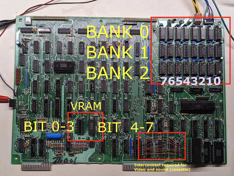
The Model 3 motherboard layout is shown above. I recommend referring to the Radio Shack Technical Service Manual for help in identifying what components might be bad on your system, but the picture should give you a head-start.
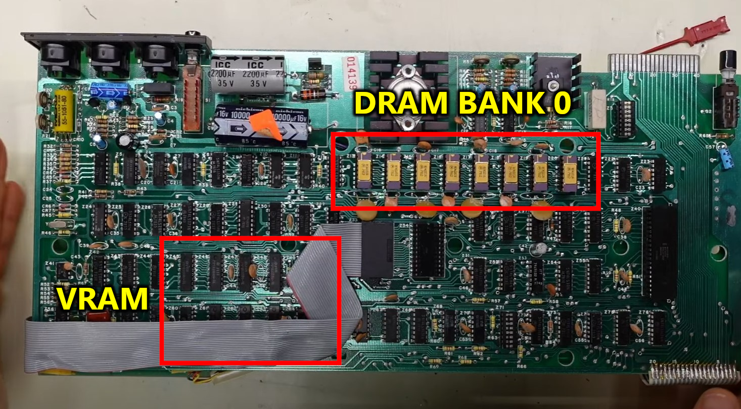
The Model 1 motherboard has only 1 bank of DRAM, which can 4k or 16k. If the system has 16k, then an additional 32k can be installed in an attached expansion interface.
For the ROM position in the Level II PCB, you must figure out which ROM is the lower ROM. You may have to look up part numbers of the chips to figure that out.
This repository will contain the assembled ROM image. To assemble, you will need to use George Phillips' zmac assembler.
Many thanks to George also for his excellent trs80gp emulator which includes integrated debugging facilities which dramatically reduced the time necessary to develop and debug these diagnostics.