
- this circuit is distributed by UNDERSCORES - an open video hardware label : it is available to purchase - as a pcb, kit or assembled unit - at underscores.shop
- the schematic for the circuit can be found here
- the pcb gerber files for the lastest version can be found here
- interactive BOM is here
- consider donating to the underscores project to help us continue creating for the commons
people in the video-art community are performing with old hardware video-mixers such as the Pansonic_WJ_AVE55 and Pansonic_WJ_MX30/50. some of these mixers have a RS232 serial port for interfacing with them digitally. this is especially useful for live performance where sequencing can assist physical actions. there are some cool examples of software specifically written to interface with these mixers (such as Freds excel app and Klifs MaxPatch ) , but there many more programs and devices that are made to interface digitally using MIDI.
the aim of this project is to create a small utility module that can _transcribe_ MIDI, a protocol used commonly in live&performance instruments to the specific RS-232 video-device specification , to better equip these retired workstations for their new life of glamour on stage
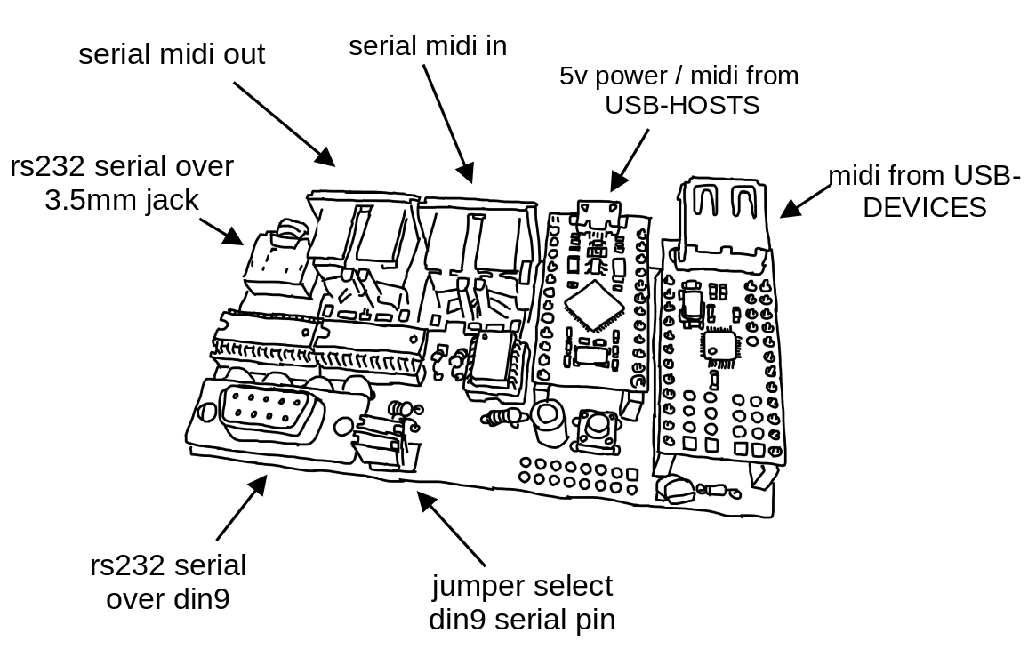
- input USB-midi from a USB-HOST such as a computer or rpi
- input serial-midi from older midi devices (din5)
- input USB-midi for a USB-DEVICE such as a korg nanokontroller or otherwise
- output RS232-serial commands over 3.5mm jack or dsub9 socket to control panasonic video-mixers and other devices
- all these interfaces are bi-directional and so can be modified with firmware to do other useful things (eg like a USB-DEVICE -> SERIAL midi converter)

this project is fully open-source hardware - all the files required to build it are included in this repo for free. if you have the time and/or skill you can contribute back by collaborating on / testing new designs, improving these docs, making demo videos/other creative content etc. you can also support the project financially by donating directing, or purchasing through the web shop.
depending on whether you are going fully diy or buying an assembled and tested unit, some of the following guides will be relavent to you. the flow would be:
parts sourcing guide (w/ notes on pcb fabracation ) - start here if you are building fully from scatch or have purchased a pcb
i try to source all the parts i can from either:
- tayda ; cheaper for common parts like resistors etc, also good for mechanical parts like switches and buttons
- mouser ; has lots more options, speciality video ic's, can sometimes cost more (free shipping on orders over 50euros)
- other ; ocationally there will be parts which will need to be sourced elsewhere - usaully either aliexpress, ebay or amazon etc...
take a look at the full_bom for this project to see where i am sourcing each part from
if you know exactly how you will use your transcribe some parts of this circuit build can be omitted. the pcb is divided into sections that are marked on silk-screen:
- A - micro-conntroller - centre : this is the brain of the circuit and is required to make it do anything. its also where USB_MIDI is received from(/sent to) usb-hosts (eg computer or raspberry pi)
- B - rs232 serial - output(/input) : for sending(/receiving) serial at rs232 levels - only omit if you are not using this board for its default / intended purpose
- C - serial midi - input(/output) : for receiving(/sending) midi messages over serial (usually on older hardware over din5 or 3.5mm jack) - can omit if you are only using (newer) hardware with USB-MIDI
- D USB-midi HOST: adds circuitry so that micro-controller can act as USB-HOST. for receiving midi messages from(/sending to) usb-devices (eg korg nanokontrol2) - can omit this if not interested in controlling from usb-devices
-
go to the tayda quick order and in bottom corner choose add from file
-
select the file tayda_bom.csv in the BOM folder (you will have to download it first or clone this repo)
-
after importing select add to cart
-
NOTE: the minimum value for resistors is 10, so you may need to modify these values to add to cart (or if they are already modified here you will need to see the full_bom for actual part QTY)
-
OPTIONAL: it is a good idea to add some dip-ic sockets and 2.54pin headers/sockets to your tayda order if you dont have them around already
- go to mouser bom tool and click upload spreadsheet
- select the file mouser_bom.csv in this folder (you will have to download it first or clone this repo), then upload my spreadsheet and next
- ensure that Mouser Part Number is selected in the dropdown above the first row, then next, process
- if everything looks correct can now put add to basket
you can support this project by buying individual pcbs from the shop. if you would rather have pcbs fabricated from gerbers directly the file you need is here
- i get my pcbs fabricated from jlcpcb - 5 is the minumum order per design
- upload the zip file with the
add gerber filebutton - the default settings are mostly fine - set the PCB Qty and PCB Color settings (you can check that the file looks correct with pcb veiwer)
- it may be best to combine orders with other pcbs you want to have fab'd since the shipping can cost more than the items - also orginising group buys is a good way to distribute the extra pcbs /costs
i often use jlcpcb because they are reliable, cheap and give you an option of colours. remember though that the cheapest Chinese fab houses are not always the most ethical or environmently friendly - if you can afford it consider supporting local companies.
a note on midi over 3.5mm trs jacks
in general newer devices send midi over usb, and older ones send serial-midi over din5 jacks. however some newer devices opt to send serial-midi over 3.5mm trs jacks (to save space on more compact designs)
transcribe has (overlapping) footprints for either serial-midi over din5 or over 3.5mm trs
unfortunately at the time that designers started using 3.5mm trs jacks for midi there was no offical standard for which pins map to midis source (midi_plus) and sink (midi_data) pins and different designers have mapped this differently on their instruments.
now there is an offical standard - TYPE A - which is what transcribe uses:
- t -> sink (data)
- r -> source (plus)
- s -> x
minimidi.world is a great resource that explains the different standards and allows you to look up the type of serial midi over 3.5mm trs that your devices have - i recommend taking a look at this if you are planning on using 3.5mm trs with your transcribe
assembly guide - start here if you have purchased a diy kit
follow this link to view the interactive BOM
-
remember to heat pad first (2-3seconds), then add solder, then continue to heat (1-2seconds)
-
Checkout the web-comic soldering is easy for more soldering advice
- in general while assembling i start placing resistors and capacitors first. placing 5 - 10 components at a time and then flipping the board to solder them and trim the legs etc.
- next i would do diodes, transistors and ic's - taking care that these are placed in the right direction (using a ic socket can be useful)
- finally i place the interface parts - rca jacks, power jack, pots and switches - make sure these have lots of solder on for structural stablity
serial-midi is most commonly sent over din5 (older hardware) J5 & J7 or trs 3.5mm jack (newer hardware) J4 & J6 - footprints for both are overlayed on the pcb so you can choose which one you would like to have
IMPORTANT: A trace needs to be cut on the usb-host-shield to allow it to be powered by 5v – see the diagram below – this is best done with a craft knife – take care not to cut any other traces accidentally.


all pins on the outer vertical lines need to be soldered to the board. In addition to this the single topmost inner pin (labeled 5v in diagram) needs to be soldered to pcb also
Start by soldering the smallest parts first: resistors, diodes, capacitors and regulators - take note of the direction on the diodes - black bar on component matching black bar on footprint
Next lets do the ic’s/sockets - make sure the direction is correct! place in and fold two corner pins to hold in place, then solder all pins. you can place the ic in now too
Now lets do the micro-controller and usb-host-shield - if you want to be able to remove them from the board you will need to solder header sockets to the board first – otherwise can directly solder the header pins
for the usb-host-shield right_row I would do a 1x2 header horizontally at the top to catch that 5v pin and then 1x11 row vertically for the rest – the left_row can just be a single 1x12 vertical header
Finally place the interface parts (eg jacks and sockets) be generous with the solder here -> this is to strengthen the mechanical connections as well as making electrical ones
Leave j8 header unpopulated – this just exposes the bootloader pins so firmware can be reset in the rare case that the pro-micro gets bricked – also leave j1 header unpopulated unless you want to power from a euro-power-header
firmware guide - for editing the code & flashing it to your micro-controller
if you have got a kit from the shop the default firmware will be pre-configured - still you probably will want to follow this so you can edit the code and update the mappings.
all underscores projects with micro-controllers use platformio with visual studio code to edit, flash and monitor the code.
- first download (and unzip) the code in this repo - easiest is as a zip or you can clone using git if you are comfortable with this
- next download, install and open visual studio code
- now open the extension tab within vscode on left vertical menu (or press ctrl-shift-x) and search for
platformioto install this extension

- connect the micro-controller to computer via usb, open the transcribe software folder (ctrl-k ctrl-o) in vscode and find the platformio commands (either in left vertical menu under platformio or little tick/arrow symbols along bottom blue bar) -
PlatformIO: Uploadshould flash the default code to your micro-controller

this guide is just an overview to get you started. the two files that you might want to look at are:
- software/src/commands.h - where the specific serial protocol commands are defined
- software/src/main.cpp - all the code that handles receiving midi and writing serial is - including the mapping function
open the src/main.cpp file in vscode and fold all functions by pressing ctrl-k, ctrl-0 - this makes reading it a bit easier:

open and take a look at the setAVE55nanokontrolMap method - we will first look at these lines:
    else if(midiParam1 == 64){setCmd(A55_A_BUS_SOURCE_1);}
    else if(midiParam1 == 65){setCmd(A55_A_BUS_SOURCE_2);}
the first line is saying: if the incoming midi message has midiParam1 set to 64, then send the A55_A_BUS_SOURCE_1 command over rs232 serial - since we can see from above that this line is within the conditional: if(midiCommand == MIDICOMMAND::CC) , then we know that midiParam1 is refering to the cc channel. we can also see in the commands.h file that A55_A_BUS_SOURCE_1 is set to the command from that panasonic ave55 specification that switches the a-bus source to input 1:
#define A55_A_BUS_SOURCE_1 "VCP:200"this line is mapping a midi message on cc channel 64 to the rs232 message for ave55 that switches the input source. this is the simplest kind of mapping - a discrete BUTTON press. however there are also mappings to functions that take parameter values also. for example the A55_A_B_MIX_LEVEL command that wipes between the a-bus to b-bus on the mixer:
if(midiParam1 == 0){setCmd(A55_A_B_MIX_LEVEL, midiParam2);}
else if(midiParam1 == 1){setCmd(A55_THRESHOLD_LUM_KEY, midiParam2);}
else if(midiParam1 == 2){setCmd(A55_CENTER_WIPE_X, midiParam2);}
else if(midiParam1 == 3){setCmd(A55_CENTER_WIPE_Y, midiParam2);}
we can see that on these mappings also the midiParam2 value is passed into the setCmd function - this is the cc value of the channel - on my controller - the position of the slider that is sending on cc channel 0. the rs232 command for this function also takes a varible input to set position of the mix:
#define A55_A_B_MIX_LEVEL "VMM:179~0"where the ~0 is a placeholder that is replaced with the hex-converted value of midiParam2. there are other ways to map midi notes to rs232 commands. there are more 'advanced' mapping functions in the code for this - for example:
else if(midiParam1 == 35){setCmdParamRandom(A55_A_B_MIX_LEVEL);}takes a button press and converts it to a random mix level. another useful mapping is taking continuous inputn (eg slider on midi controller) and convert this to a STEP of different discrete commands - for example:
else if(midiParam1 == 17){setCmdStepAVE55(A55_A_BUS_MOSAIC_OFF, midiParam2, 76, 6);}
else if(midiParam1 == 18){setCmdStepAVE55(A55_A_BUS_PAINT_OFF, midiParam2, 82, 6);}
these mappings STEP between sending 6 different rs232 commands on a single slider - so you can set all the mosaic/paint effect levels in one turn. another useful 'advanced' mapping function is the SWITCH:
else if(midiParam1 == 50){setCmdSwitch(MX50_A_BUS_EFFECT_ON, MX50_A_BUS_EFFECT_OFF, 3);}this will SWITCH between sending the on and off commands when the same midi command is send (the third parameter input 3 is a unique index reference to store the on/off state in memory between messages)
these are just some examples of the ways that code can be used to perform these mappings. if you are interested can see more in the code directly or write your own mapping functions!
operating guide - start here if you have purchased an assembled unit
how the circuit works
[coming soon]
contributing guide
if you would like to contribute back to these projects in some way but dont know how the best thing (for now) would be to reach out to me directly ( tim@cyberboy666.com or @cyberboy666 on scanlines forum) - i will be happy to help
This circuit is distributed through UNDERSCORES – open video hardware label – visit underscores.shop for more info
The pcb was designed using KICAD
Everything from gerbers, cad files, panels and documentation is freely available online and distributed under CC-BY-SA / open-source licenses – help us contribute to the commons !
Ask any questions or start discussions related to this project on the scanlines.xyz forum – an online community space dedicated to diy av / electronic media art
You can contact me directly at tim (at) cyberboy666 (dot) com Please get in touch if you are interested in hosting a workshop !

Thanks to Gilbert Sinnott for helping with initial experiments. to Bastien Lavaud for circuit advice, always. To Ben Caldwell for project advice. To everyone who has or will contribute ♥♥♥