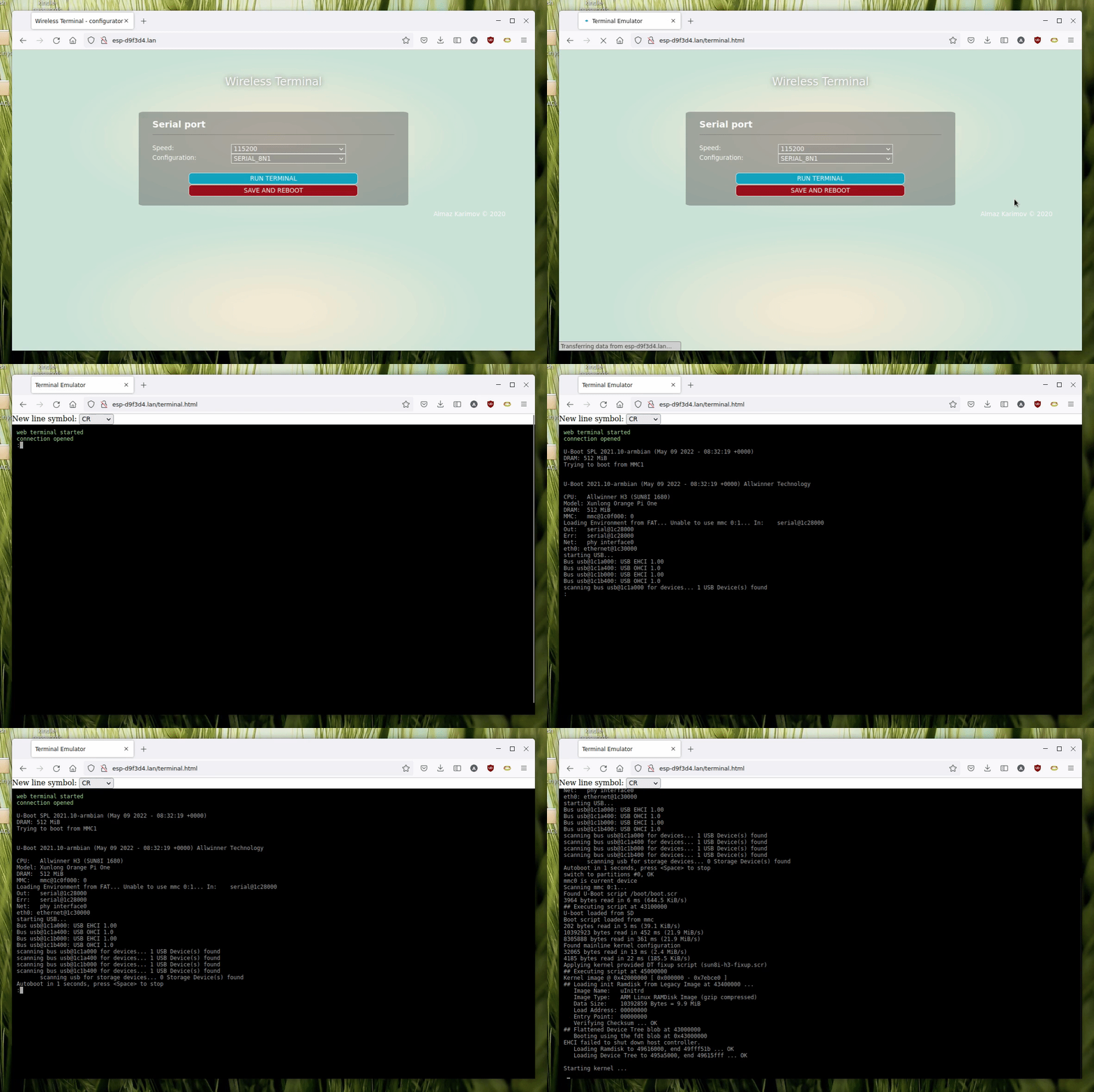
Assume you have a serial accessible device (like Raspberry Pi or ESP32 node) that falls into boot loop. If for some reason it is not possible or not convinient to bring your laptop to the device proximity, you can attach Wireless Terminal to the device and connect to it via WiFi. Next you use ESP8266 hosted web-based terminal as if you were connected directly.
- Using WiFiManager for Wifi configuration - no hardcoded passwords. When run for the first time (or no known networks present), configure via captive portal, then settings are saved and ESP8266 will connect automatically.
- Configure UART speed and bits/parity settings (saved between reboots)
- RGB status led - flashes when client connects and when data going in both directions
Code written using Visual Studio Code with PlatformIO plugin. Configuration is placed in platformio.ini file, adjust if you use your own board. Rest of the configuration is in application.hpp file, please have a look if you need to do some adjustments.
UART0 is used for both programming and connection to target. After device start UART0 is reconfigured to use GPIO13/15 for communication, so default GPIO01/03 that normally connected to programmer via UART-USB bridge is not interferring with target device.
UART1 is used for debug output, since RX is not availbale only TX is present on pin GPIO02, normally it is not connected to anything, so you need to attach external USB-UART bridge.
RGB led is optional and attached to pin GPIO12. WS2812 led is expected, but if you don't have one, connect out following line in the application.hpp file and pin will be used in normal LED (on/off blink) mode
#define PIN_STATUS_LED_RGB
- Build solution in platformio
- Upload filesystem image using
Upload Filesystem Imagetask - Upload firmware using
Uploadtask - (First time) Upon power on ESP-XXXXXX network will appear, connect to it using your phone and you will be redirected to wifi configuration page
- When configured device restarts and from this moment on it will connect to known network autmatically. Your phone will switch back out of ESP-XXXXXX network
- Go to ESP-XXXXXX page to configure UART settings and enter terminal. Alternatively you can check what IP address device has in router logs or using debug output on UART1
- (Alternatively) Please use TCP terminal via telnet on 23 default port:
telnet 192.168.4.1 - Connect target device on GPIO15/13 (TX/RX) and you should be able to sent and receive using both described methods
The emulator is implemented using the jQuery Terminal Emulator: https://terminal.jcubic.pl/ library
I've developed custom PCB for this device. This is base don standard ESP12F module and has onboard RGB LED as described above. What's more it has onboard Li-Ion battery (14500 size), alternatively can be powered by external Li-Ion battery via standard connector. Also it has battery management circuit on the board, with charhing from built-in USB port. same port is used for serial flashing.
As usual schematics and design files are available under hardware section.
Soon to ba available on Tindie


