I wanted to use a single 27C400 for the extended ROM in my CDTV because 2x 27C1000's are a pain. A single socket for the rom also makes debugging easier because I can use a single flashed based rom. This means I can easily pop in CDTV Land's replacement ROM and easily burn or test future updates.
The second goal was to relocate the CPU socket in such a way to allow an accelerator such as a TF536 or 020-TK to be installed without interferring with caps and in such a way that by soldering everything together the case for the CDTV could still be closed.
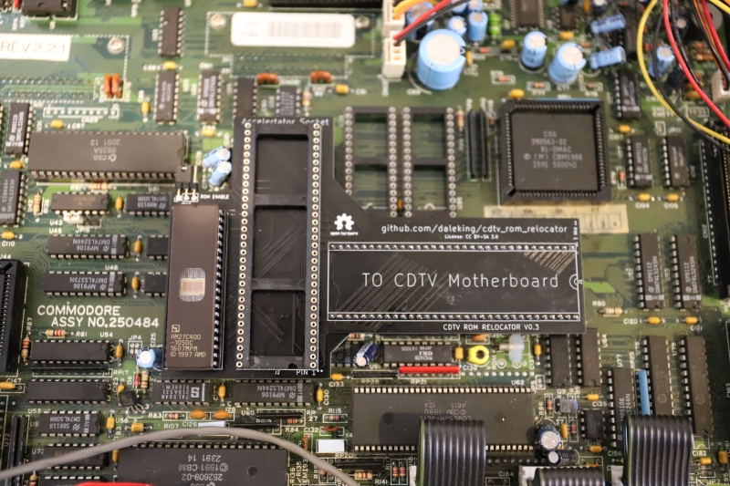
Hence the CDTV ROM Relocator was born. It's a simple relocator with some decoding logic for the extended ROM and a jumper to disable/enable the rom (since JP15 on the motherboard only drives logic to the motherboard roms).
By trimming the CPU pins and soldering together a sandwich, the case can be closed.
If you want to build one you can try the gerbers from here.
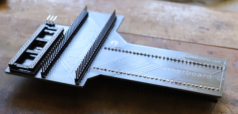
This is the bare relocator with an empty 68000 socket. Installing the original 68000 will still work and the case can still be closed.
Note! If you install a socket for the accelerator you will likely not be able to close the case. I recommend soldering the accelerator directly to the relocator but please do this at your own risk!
Here we have an installed TF536 and CDTV OS 2.35 on a single 27C400.
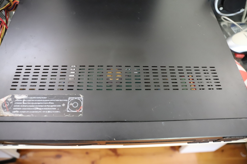
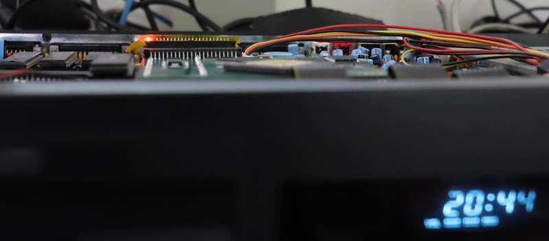
Case closed! The tallest component is the ROM, which still has a mm or two before it touches the case.
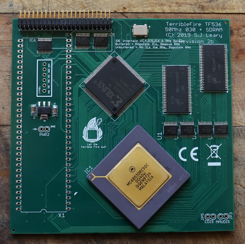
We'll need an accelerator. I like the TF536 with the firmware from here which disables the flashy boot rom on the TF536 (that is in the same address space as the extended ROM).
You will also want a right angled IDE header, not a straight one. This means the cable connector is nice and flat.
You will want to solder down and trim the legs of your CPU. In hindsight I would raise the CPU of the board by a few mm and just solder the leads short. There is enough height left for the CPU to sit a little proud but please do test fit before soldering.
I used regular pin strips between the relocator board and the TF536. The plastic at the bottom is the height I chose as a safe distance between the two PCBs.
Here they are just before soldering together. Check there is nothing that will short. I used a bit of cardboard to keep everything spaced nicely and as a bit of extra protection in case the boards got smooshed by the case.
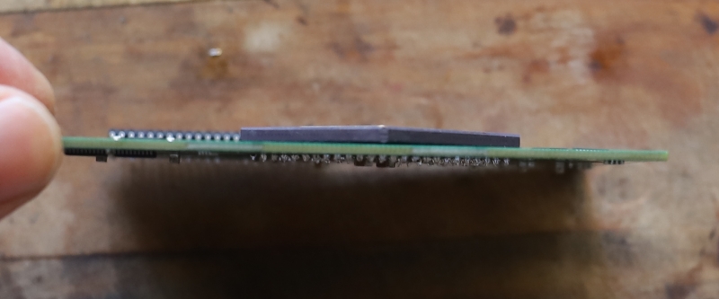
Testing installed height. In my case the ROM is the tallest component. You could try and find a lower profile DIP socket for the ROM.
