##About
The Wedge Maker for ArcGIS is an ArcGIS tool that allows the user to create wedge and arcband (a wedge with a part of the cone of the wedge erased) shapes.
###Usage
The user chooses one of the two tools within the ArcGIS toolbox. The different tools allow the user to specify either the two lines of bearing or the line of bearing and swath that will help define each wedge/arcband. After opening either tool in ArcGIS, the user specifies the following:
- The input point feature class
- The names of the fields that specify either the two lines of bearing or the bearing and swath that define the angular extent of the wedges.
- The name of the field that contains the outer radius of each wedge.
- Optionally, the name of the field that contains the inner radius of each arcband.
- The output polygon feature class.
The entries in the radius field(s) must be in the format required by ESRI's ArcGIS Buffer tool. For example, "5 MILES", "3.41 kilometers", or "23 NauticalMiles". The units must be specified. If the user provides an inner radius field, then input rows that contain an entry in that field will be made into an arcband shape by creating the full wedge shape and then erasing from the center of the wedge outward by the distance specified in the inner radius field. If the user provides an inner radius field, the user may still leave some entries in the inner radius field blank, in which case a full wedge will be created for that row.
###Methodology (summary)
For each input point, the tool reads the point's coordinates and attributes. The tool buffers the point by the outer radius distance, and then calculates the vertices of a triangle that can be used to clip or erase from the buffer in order to leave the desired wedge shape. Then, if the user wanted an arcband shape, the tool buffers the point again by the inner radius distance and then erases from the wedge shape with the buffer. Finally, the tool combines all of the output wedge/arcband shapes into a single polygon feature class and uses the Join Field tool to join the input point feature class's attribute table to the output polygon feature class's attribute table.
###Methodology (in-depth)
How can we create a wedge or arcband based upon the tool's inputs? The answer is with some ingenutiy and triangle trigonometry.
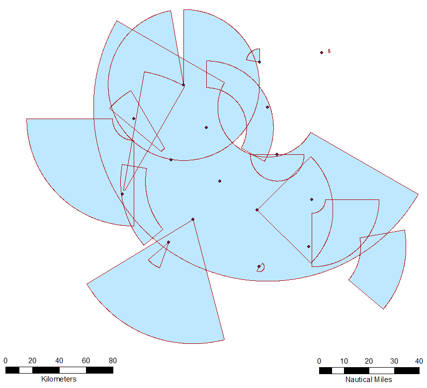
In the above graphic, suppose that we are trying to create the wedge shape in dark gray. We can do so by buffering the origin point of the wedge by the length of the outer radius and then clipping it by the clip triangle shown in the graphic. In order to do so, we have to create the clip triangle, which means that we have to calculate the coordinates of its vertices. One vertex is the same as the wedge origin, and so we must calculate the coordinates of the other two vertices.
Knowns:
- The coordinates of the origin point of the wedge
- The angles of the two lines of bearing of the wedge
- The outer radius of the circle
To do so, we'll construct the clip triangle in such a way that it will have the properties we need. First, call the angle between the first and second lines of bearing theta. Draw a radius of the circle such that it bisects the angle theta. Next, draw a line that is tangent to the circle at the point where the radius intersects the circle. Finally, draw lines from the origin point of the circle that extend along the lines of bearing of the wedge until they intersect the line that is tangent to the circle. These lines define the clip triangle.
Note that the angle between the radius and the tangent line is a right angle, meaning that the large clip triangle can be split into two smaller right triangles. Now consider just the upper of the two right triangles in the graphic. We know the size of the angle formed by the line of bearing and the radius: it's simply (theta/2) because we deliberately chose this radius because it bisects theta. We know the length of the radius because it's just the length of the outer radius of the wedge. With this knowledge and with triangle trigonometry, we can calculate the length of the hypotenuse of this upper right triangle with the formula abs(r/cos(theta/2)). The length of the hypotenuse is the distance between the origin point of the wedge and this vertex of the clip triangle.
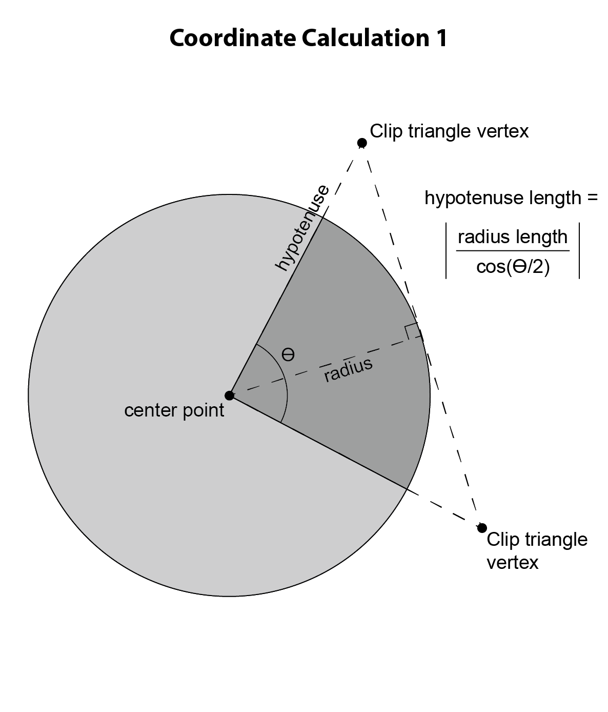
Armed with this knowledge, now consider the right triangle shown in the above graphic. The hypotenuse of this right triangle is the same as the hypotenuse of the previous right triangle. By calculating the lengths of legs X and Y of the right triangle, we can calculate the coordinates of the clip triangle vertex. Now consider the angle alpha. Its measure is simply equivalent to that of the first line of bearing of the wedge! With more triangle trigonometry, we can calculate the length of leg X with the formula sin(alpha) * hypotenuse, and the length of leg Y with the formula cos(alpha) * hypotenuse. Then, by adding the length of leg X to the X coordinate of the origin point of the wedge, we get the X coordinate of the clip triangle vertex, and by adding the length of leg Y to the Y coordinate of the origin point of the wedge, we get the Y coordinate of the clip triangle vertex. In this example, we are working in the upper right quadrant of the circle, but the math is similar no matter in which quadrant of the circle we are. By identical math, we can calculate the coordinates of the final vertex of the clip triangle, and then use the clip triangle to clip the buffer, resulting in the wedge shape.
Once the wedge shape is made, we can easily create an arcband shape if the user requests it. We simply buffer the origin point of the wedge again, this time by the inner radius length, and use that new buffer to erase from the wedge shape.
####Other Considerations
What if the user wants a large wedge of more than 180 degrees? In this case, the math is identical. The only difference is that the tool uses the clip triangle to erase from the circular buffer, instead of using it to clip the circular buffer.
What if the user wants a semicircle of exactly 180 degrees? In this case, the math fails because we would have to create a clip triangle with an internal angle of 180 degrees. In other words, if you imagine a wedge getting wider and wider, and also imagine the clip triangle that would have to be constructed in order to create such a wedge, the clip triangle gets flatter and flatter (and fatter) as the wedge approaches 180 degrees. At exactly 180 degrees, the clip "triangle" is flat, and no meaningful clip process can take place. How to solve this problem? There are multiple ways of doing so, but the tool's solution is simply to create two 90-degree wedges back to back and dissolve them together.
A similar problem arises when the user wants a wedge that's very close to 180 degrees. The math works, but because the clip triangle gets wider and wider as the wedge's angular measure approaches 180 degrees, the GIS will eventually be unable to handle the math behind the clip triangle as the clip triangle's coordinates will exceed the boundaries of any possible projection. To prevent this situation, the tool checks whether a wedge's angular measure falls between 135 and 225 degrees. If it does, the tool uses the two-wedge method described in the previous paragraph.
###Notes
Because the tool performs distance calculations, the tool requires that the input point feature class be projected. The tool attempts to detect if the user provides unprojected data (such as WGS84 lat-long data) and halts operations if it detects unprojected data. If the tool fails to detect the unprojected data, it will still run by the output wedge/arcband shapes cannot be considered reliable.
The tool considers due North to be 0 degrees bearing and bearing increases in a clockwise direction. The tool allows input lines of bearing less than 0 degrees and greater than 360 degrees. If the user provides an identical line of bearing for both the start and end of a wedge shape (or provides a swath width of 0 degrees), the tool interprets this as a 0-degree wedge and skips its creation altogether. If the user provides two lines of bearing that differ by a multiple of 360 degrees but not 0, then the tool interprets this as a 360-degree wedge. For example, two input lines of bearing of "120" would result in no wedge being created, but input lines of bearing of "120" and "-240" would result in a full circle shape being created. If the difference in input lines of bearing is greater than 360 degrees, then the tool will reduce the difference by 360 degrees repeatedly until both lines of bearing are between 0 and 360 degrees. For example, input lines of bearing of "120" and "540" are equivalent to input lines of bearing of "120" and "180".
###Origin
Wedge Maker was developed at the National Geospatial-Intelligence Agency (NGA) by a federal government employee in the course of their employment, so it is not subject to copyright protection and is in the public domain.
###Pull Requests
If you'd like to contribute to this project, please make a pull request. We'll review the pull request and discuss the changes. This project is in the public domain within the United States and all changes to the core public domain portions will be released back into the public domain. By submitting a pull request, you are agreeing to comply with this waiver of copyright interest. Modifications to dependencies under copyright-based open source licenses are subject to the original license conditions.