This project started because I needed a 10 MHz oscillator that could run with VCC at 3.3V to provide a clock signal to a 3.3V FPGA. I do have some 10 MHz full-can oscillators, but I don't have a datasheet for them, and it's not clear whether they are rated to run at 3.3V. So, I designed a small PCB with the same pinout as a full-can oscillator which uses a surface mount 74HC04 and a low-profile HC-49US through-hole crystal to generate a 10 MHz square wave.
The schematic and PCB design were (of course!) created using KiCad.
Obligatory photo:
The assembled module is approximately the same size as a standard full-can oscillator, and has the same pin spacing. Note that unlike a "real" oscillator, pin 1 isn't an input that you can ground to disable the clock output, so if you need that functionality, this module won't work.
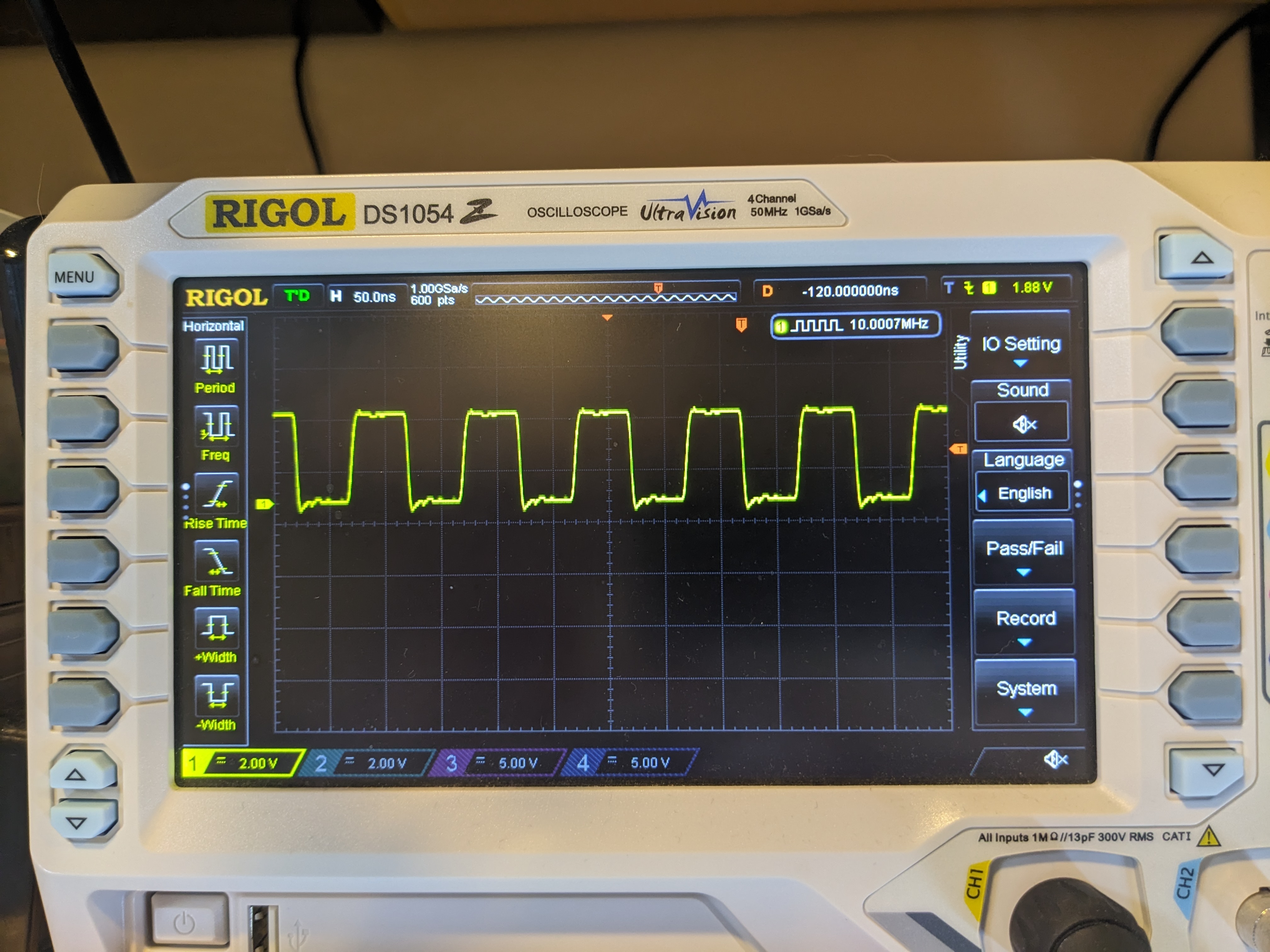
It produces a reasonable 10 MHz square wave:
Parts list:
| Symbol | Part | Note |
|---|---|---|
| R1 | 1 MΩ 0805 resistor | |
| R2 | 1 kΩ 0805 resistor | |
| C1 | 100 nF 0805 capacitor | decoupling for the 74HC04 |
| C2, C3 | 22 pF 0805 capacitor | loading caps |
| U1 | 74HC04 in a TSSOP-14 package | inverters for oscillator, output |
| Y1 | 10 MHz HC-49US low-profile crystal | parallel resonance (not series) |
| J1–J4 | Male header pins | whatever kind you prefer, I like the round ones |
The resistors and capacitors are 0805 package (imperial measurement). I got most of the components from LCSC. The boards were fabbed by OSHPark. (You can just upload Oscillator.kicad_pcb to OSHPark, no need to generate Gerbers, drill files, and whatnot.)
The circuit will likely work with other crystal frequencies (I think you would just need to select loading capacitors appropriately.)
I'm not particularly skilled at surface mount soldering, but I had no trouble assembling these. I used drag soldering with lots of flux gel for the 74HC04, with only tiny amounts of solder on the tip of the iron. For the resistors and capacitors, I melted solder onto one pad, used tweezers to position the component (with the solder melted), then soldered the other pad.
This board is made available as public domain (CC0). I provide no guarantee that it will do anything useful: use it at your own risk.
Oscillator PCB by David Hovemeyer is marked with CC0 1.0

