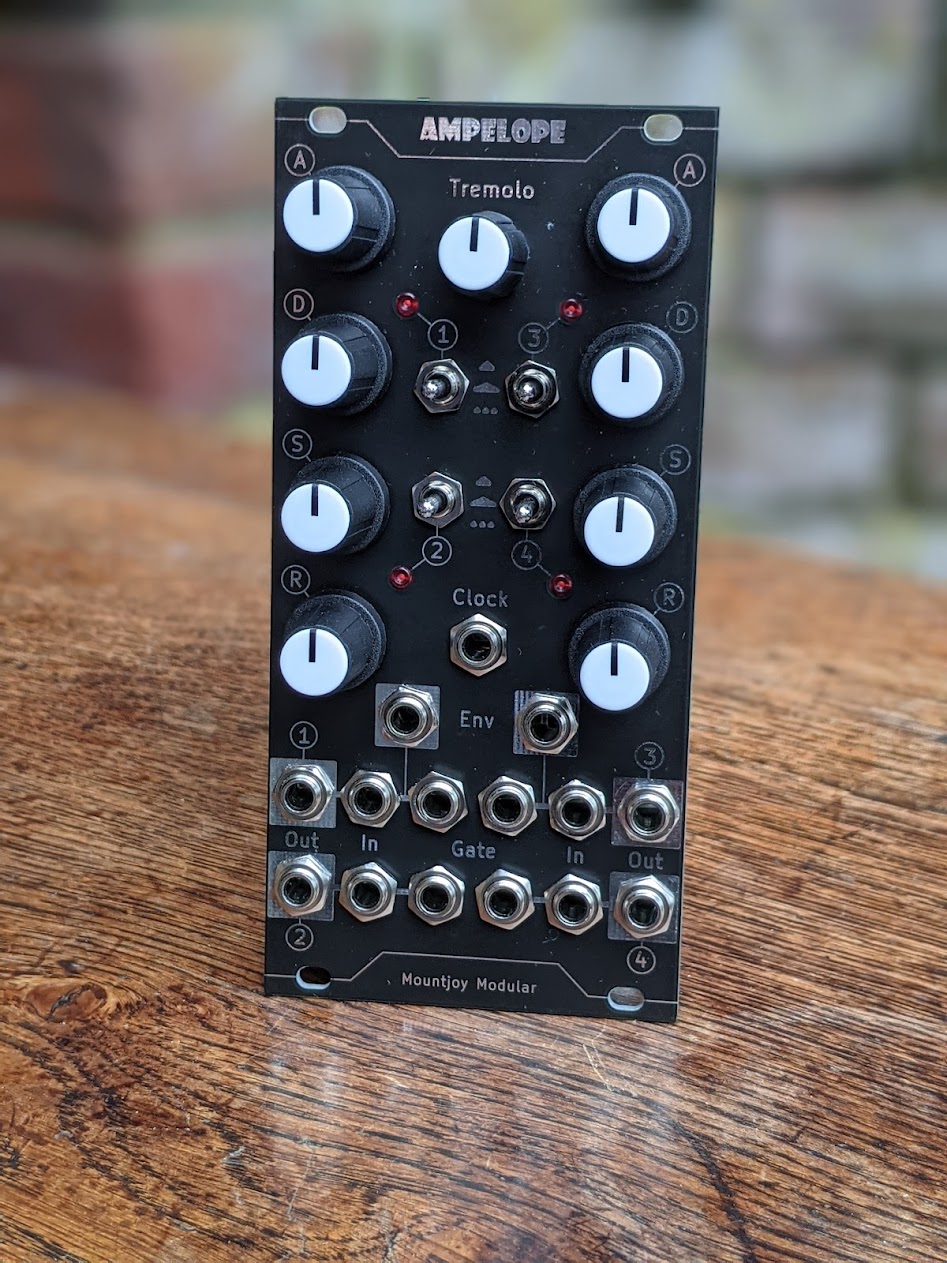
Ampelope is a four-channel combined envelope and VCA Eurorack module incorporating a tremolo effect. Each channel can be switched between a fast envelope time, a slow envelope time or a slow envelope with a sine tremolo modulating volume.
The envelopes are loosely modelled on an analog envelope (Roland System 100 type circuit) and feature analog correct capacitor charge/discharge characteristics.
Channels 1 and 2 share the same Attack/Decay/Sustain/Release (ADSR) controls, as do channels 3 and 4. This makes the module particularly suited to dual stereo operation. However each channel has its own gate control allowing independent control of four signals.
The gate controls are normalled in a cascade configuration. For example in dual stereo use gate 1 will be normalled to gate 2 and then a separate gate applied to channel 3 will control channels 3 and 4. In addition gate 1 is normalled to the Doepfer standard gate signal on the 16 pin Eurorack header.
The tremolo control can be clocked or free-run. When clocked the Tremolo potentiometer sets the speed of the tremolo to a multiple of the clock. The tremolo effect applies a sine wave modulation to the envelope.
In addition to the envlopes internal connection to the VCA, envelopes 1 and 3 are available on the front panel and envelopes 2 and 4 on a pin header on the back.
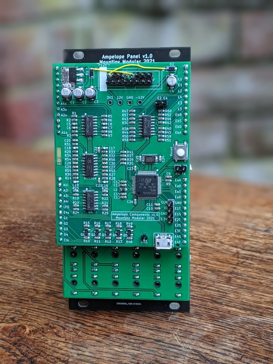
The module is controlled by an STM32G431 microcontroller which contains four 12-bit DACs. These are used to generate the four envelopes.
The MCU runs at 170MHz and the envelopes samples are generated at 48kHz. The front panel potentiometers are digitised using the MCU's internal ADC. The MCU features a hardware CORDIC peripheral which is used to generate the exponential curves used to model an analog envelopes capacitor charge/discharge characteristics. The CORDIC co-processor is also used to generate the tremolo sine wave.
The MCU's USB peripheral is also connected on the reverse for configuration and upgrade purposes.
The VCA used is an Alpha AS3364 quad linear VCA IC (https://www.alfarzpp.lv/eng/sc/AS3364.php). The MCU outputs the envelopes via its internal DACs at 0V to 3.3V range. This is scaled to 0V to 2V which is the VCA fully closed/fully open range. The envelopes are also amplified to 0V to 8V for control of external modules.
Three TL074 op-amps handle buffering and amplification. NPN transistors provide voltage limiting to incoming gates. The power supply uses a linear regulator to generate the 3.3V digital and analog voltages used by the MCU.
The module uses a 3 stacked PCB configuration. The components sit on a 4-layer daughter board connected with headers to the 2 layer control PCB holding the LEDs, potentiometers, switches and sockets. This is then bolted to the front panel, also constructed as a 2 layer PCB.
All schematic and PCB layout carried out in Kicad version 5.99.

