This project is based on Arjan te Marvelde / uSDR-pico, from https://github.com/ArjanteMarvelde/uSDR-pico . I strongly recommend you to take a look there before trying to follow this one.
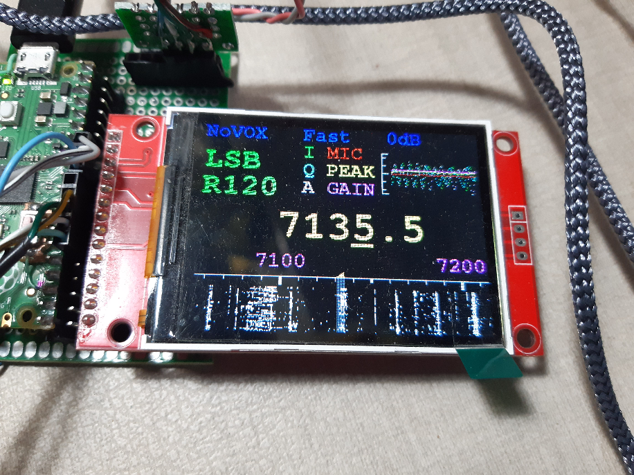
My intention was to include a waterfall or panadapter to the uSDR-pico project, for this, I included an ILI9341 240x320 2.4" TFT display without touch, and also, changed the software to generate the waterfall.
Initially, I have used Visual Studio, but after some considerations, I ported all code to Arduino IDE. So, to compile and run this code you need the Arduino IDE installed for a Raspberry Pi Pico project.
I also, chose not to change the original software as much as possible, and focused on the waterfall implementation, mostly in the dsp.c.
I used the word "uSDX" instead of "uSDR" to name some files. This was a mistake. My intention was to follow Arjan's project with the same names.
Initial tests video: https://youtu.be/0zGAnkRjizE
AGC and Visual Scope video: https://youtu.be/BiaS002xZfw
Transmission test video: https://drive.google.com/file/d/1Rr4CVPphtcBfMTgRN5z8F7xxByQ_1ybG/view
There are also some messages related to this project at:
https://groups.io/g/ucx
Subject: uSDR-pico on GitHUB
Initial msg: #15923 · May 26 2022
There is a uSDX_TX folder with code to test RF modulation using phase and amplitude, the same method used at the uSDX project (https://github.com/threeme3/usdx). If the test works on Pico, it will be included as an option to the main project.
- There are 3 ADC inputs: I, Q and MIC (if we remove the VOX function, we could remove the MIC ADC during reception, this will increase the ADC frequency for I and Q, improving the frequencies we can see at the display - for now I will keep it like the original).
- The max ADC frequency is 500kHz, I have changed it to 480kHz (close to the original) to make the divisions "rounded".
- The ADC for audio reception has frequency of 16kHz (close to the original). I have tested higher frequencies, but the time became critical, without so much benefit.
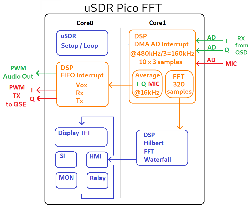
- The max ADC frequency for each sample = 480kHz / 3 = 160kHz (because there is only one internal ADC used to read the 3 inputs in sequence).
- With 160kHz of samples, we can see 80kHz range after the FFT, but if we apply Hilbert to get the lower band and the upper band, we get two bands of 80kHz, one above and one below the center frequency.
- There is no time to process each sample at 160kHz and generate the "live" audio, so I use this method: Set the DMA to receive 10 samples of each ADC input (10 x 3 = 30) and generate an interrupt. So, we get 16kHz interrupts with 10 x 3 samples to deal. For audio, we need only one sample at each interruption of 16kHz, but to improve the signal, I made an average from the last 10 samples to deliver to audio task (this is also a low pass filter). For FFT, we need all samples (raw samples), so they are copied to a FFT buffer for later use.
- There is also no time to process the samples and run the audio receiver part at 16kHz, so I chose to split it. The interrupt and buffer/average part is done at Core1, and the audio original reception is in the Core0.
- Every 16kHz interrupt, after average the I, Q and MIC, these samples are passed to Core0 to follow the audio reception tasks.
- For the waterfall, when we have received 320 I and Q samples, it stops filling the buffer and indicates to the Core1 main loop to process FFT/Hilbert for a new graphic line.
- The original processes run at Core0, every 100ms.
- There is a digital low pass filter FIR implemented at the code (in the original too) that will give the passband we want for audio. This filter was calculated with the help of this site: http://t-filter.engineerjs.com/ The dificulty is that the number of filter taps can not be high (there is no much time to process it), so the filter must be chosen carefully.
- Please consider that this waterfall is not perfect, I had to let go of some rules to make it.
- Block diagram at "Arduino_uSDR_Pico_FFT.png".
Input: We sample each signal I, Q and MIC at 160kHz, so it is necessary to have a hardware low pass filter for 80kHz on each input (anti-aliasing filter). If the input filter is set to lower than 80kHz, the waterfall will show less than +-80kHz of signals. If the input filter is set to higher then 80kHz, the audio and the waterfall could peek some signals greater than 80kHz and treat them as lower than 80kHz (this is the aliasing problem).
Output: We deliver an audio signal at 16kHz sample frequency, so we need a hardware low pass filter for less than 8kHz at the output. The sample frequency will be present and needs to be removed as it is an audio frequency.
- Core0 and Core1 are too much connected and affect each other. This made me lose some painful hours...
- There are only 3 ADC ports available.
- There are some reports at internet about the low quality of the RP2040 ADC readings.
- I am using Arduino IDE version 1.8.19 in Linux/Ubuntu
- Lib used: TFT_eSPI by Bodmer
- IMPORTANT: Use the comments at beginning of .ino file to "adjust" the library files to the project.
- Boards Manager: Arduino Mbed OS RP2040 Boards. My version is 3.0.1 (If I update it, I will need to adjust the library files again, so I will leave it for later).
- Do not include EarlePhilhower library (it is just conflitant with Mbed)
- Board: "RaspberryPiPico" > Arduino Mbed OS RP2040 Boards > RaspberryPiPico
- The code files have cpp type, but the code itself is in C (cpp type is used to help in some compiler issues).
- Inclusion of ILI9341 on free pins, using SPI1, and removing the LCD display.
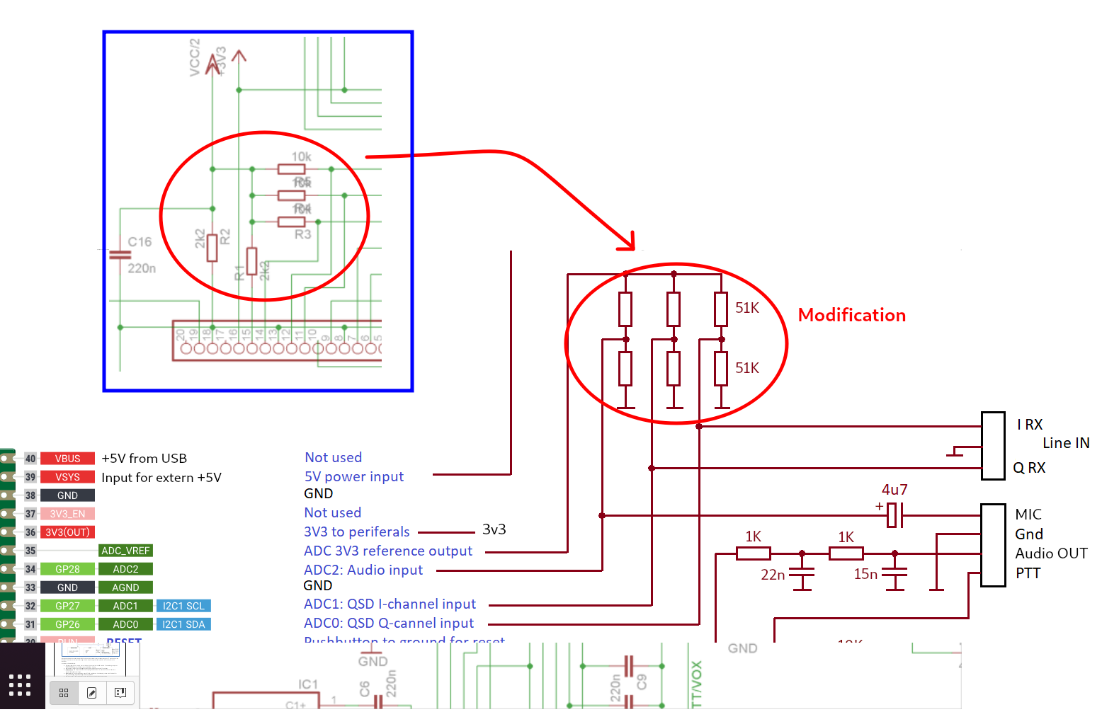
- Schematic diagram at "FFT_LCD_pico.png".
- I noticed that changing the signal in one ADC input, changed the other inputs signal through the resistors for setting half Vref. To solve this, I changed the circuit to have a separate resistor divider for each ADC input.
- Use input/output filters for Nyquist considerations (see above).
- Obs.: at the initial test video, I used only the RC output filter shown in the schematic, and for input filter, only what is already inside of the Softrock RXTX Ensemble.
Ago17 2022
- Included sketch folder uSDX_TX to test the Phase and Amplitude TX method.
Ago07 2022
- PTT input corrected. Now it uses the falling or rising to turn off and on the PTT.
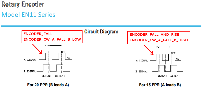
- Including options for encoder at hmi.cpp: ENCODER_TYPE ENCODER_DIRECTION
Ago05 2022
- Now the frequency changes at each encoder step (I am using EC11 encoder and it changed the frequency at every second step)
- Plot to the waterfall improved to spend less time
- Included separate audio filters for CW and AM
- Included side tone for CW TX
- Writing to display and programming Si5351 only when necessary (finally)
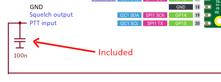
- PTT debounce reduced to allow CW TX (** it needs a 100nF capacitor from PTT pin to ground **)
Jul20 2022
- Waterfall: Changed to fall instead of going up
- Waterfall: Frequency scale moving with main frequency
- Waterfall: Shadow indicating the reception zone
- AGC attack faster
- It shows the reception signal level implemented from audio output and gain
Jun24 2022
- Few display corrections: central triangle, mode text overwriting.
Jun10 2022
- AGC uncommented and adapted to work.
The AGC is only used at the output audio, not for waterfall. - A visual scope was implemented to allow visualization of some internal variables.
The variables plotted are:
- I, Q and MIC = ADC inputs
- A = output audio
- PEAK = average of absolute(A)
This gives an input signal level for AGC (min in the middle of the scope height, max at the top) - GAIN = AGC result.
If the PEAK is high for some time, it decreases the GAIN. With PEAK low, increases GAIN.
Gain has 32 steps:
1 = min AGC gain (almost in the middle of the scope height)
32 = max AGC gain (limited to 25 at the top of scope) - Obs.: Scope limits: -25 < y < 25 0 < x < 100 (each 'x' dot time = 1/16kHz)
- Obs.: Variables are scaled to fit in the scope height.
- I, Q and MIC = ADC inputs
- The signal level meter at the display does not change because it is fixed at the original code (the level depends on the software as well as the hardware).
- Improve the S meter, at least to show the AD input signal level.
- The AGC needs to be improved as the audio still saturate at beginnig of strong signal
- Include RIT (receiver incremental tuning)
- Reduce the minimum step to change the frequency to 50Hz or less
- Verify why the switches do not work some times (at least for me)
- Check the trasmission on all modes
- Storage the last state to recover it at the next power up (SD card? Internal Flash doesn't work, it needs to stop interrupts)
- Band selection with setup for each one (correspondence to the filter bands)
- Tests: reception/transmission SSB... menus... switches/debounce... display appearance
The code and electronic designs as well as the implementations presented in this repository can be copied and modified freely, for non-commercial use. Use for commercial purposes is allowed as well, as long as a reference to this repository is included in the product.
