Simple LED Control project for Raspberry Pi Pico and Pico W with MQTT (and Home Assistant auto-discovery).
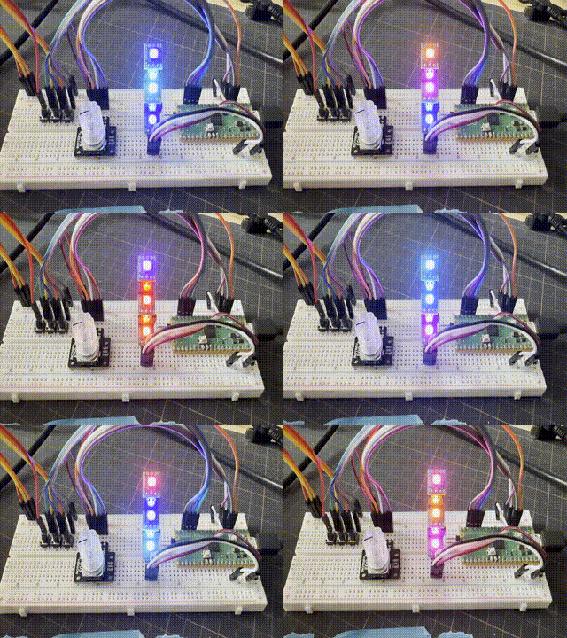
- Example Build
- Hardware
- Usage
- Before you start
- Prepare build environment
- Grab the Pimoroni libraries
- Clone this repository
- Prepare project environment
- Build
- Flash
This build uses the DFRobot mmWave sensor to detect presence, and the Sparkfun RGB Rotary Encoder with built-in push button. The rotary encoder is used to control the LED strip, and the "C" button is used to turn the LEDs on/off.
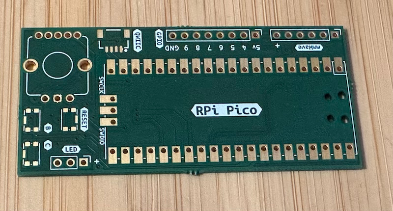
PCB:
The PCB can be ordered from AISLER, here or from another manufacturer of your choice.
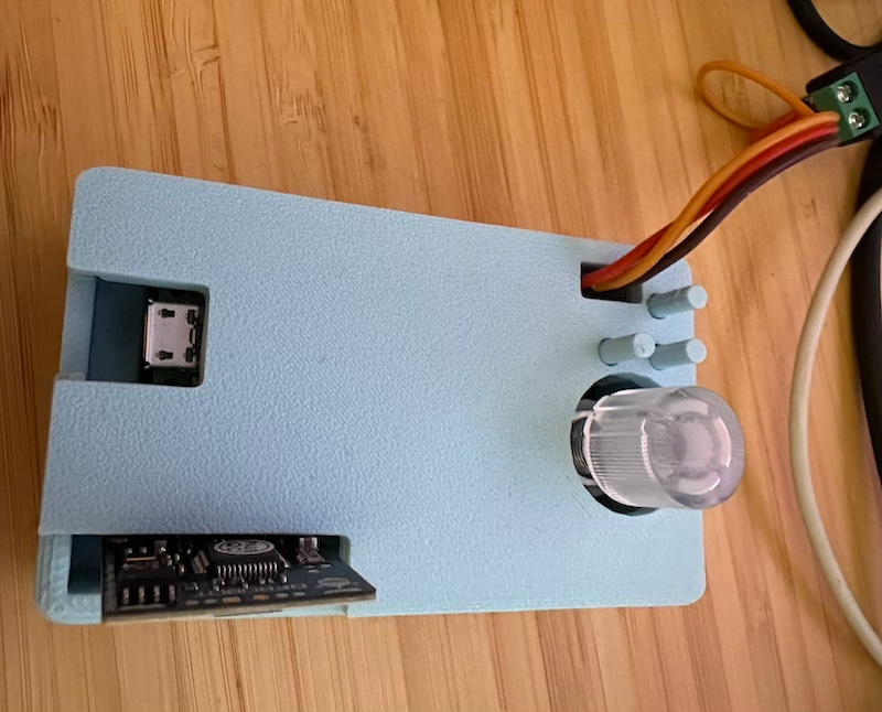
3D printed enclosure:
The enclosure design files are stored in Tinkercad, here.
Schematic, PCB files and additional photos can be found in ./pcb1 and the 3D printed enclosure files and photos are in ./enclosure.
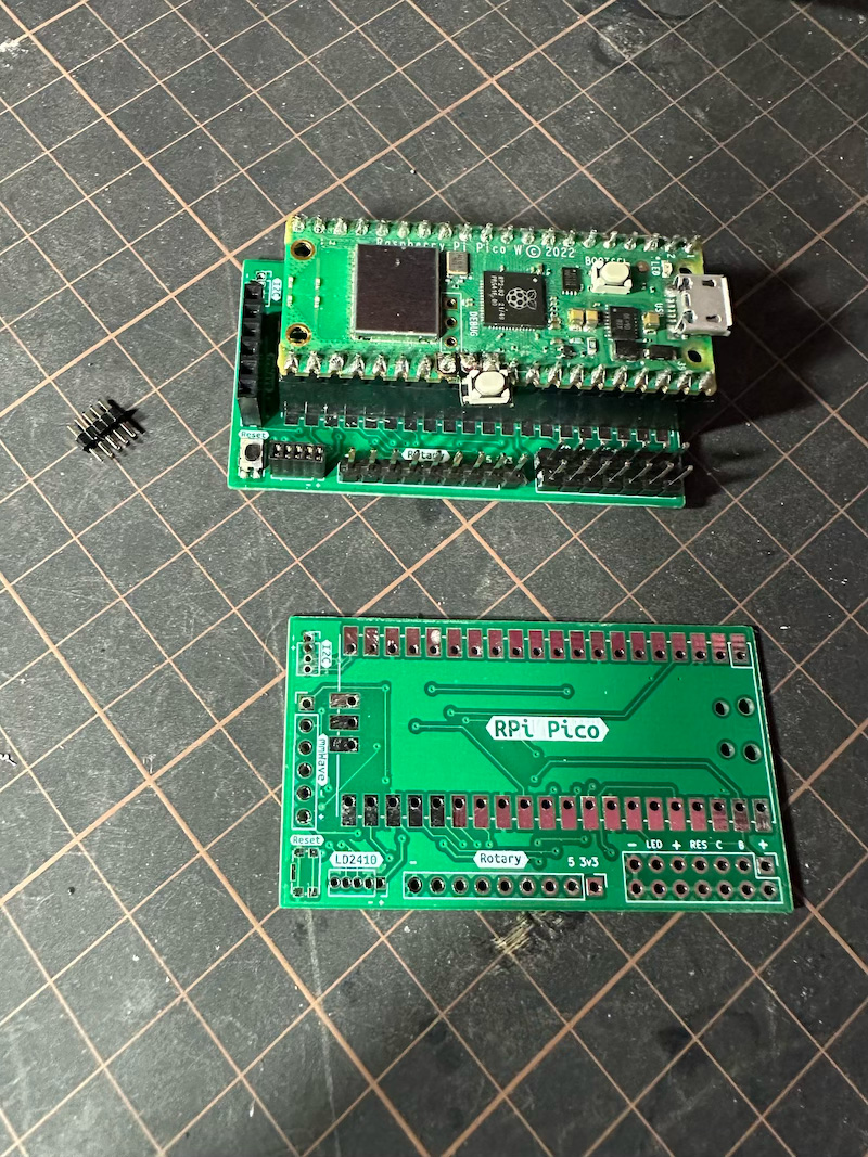
This is more of a dev board, still has sockets for DFRobot mmWave or a LD2410 sensor, the Sparkfun RGB Rotary Encoder with built-in push button and additional button breakouts.
PCB:
Schematic, PCB files and additional photos can be found in ./pcb2.
- Raspberry Pi Pico or Pico W
- A WS2812/SK6812 LED strip or a bunch of NeoPixels
- Optional: Sparkfun RGB Rotary Encoder with built-in push button, and optionally the breakout
- Optional: An extra button (button "B") if you want to load/save your colour schemes.
- Optional: Another extra button (let's call this "C") if you want an instant on/off button.
- Optional: Captain Resetti to return to default colours, or just replug the board.
- Optional: DFRobot mmWave Radar to turn on/off the lights when you enter/leave the room.
- Read the uberguide if you haven't...
Only a single (right) side of the Pico is used for connections to allow for creative mounting options.
- WS2812/SK6812 LED strip: Data on
GP28. Power with 5V (VSYSin a pinch) andGND. - (Optional on the Pico W) Rotary Encoder with LED and button: 8 connections, believe or not!
- LED connections: Red to
GP18, Green toGP19, Blue toGP21 - LED common anode to
3v3(Pin 36) - Rotary encoder: A to
GP16, B toGP17, C toGND(Pin 23) - SW to
GP20
- LED connections: Red to
- Optional: Button "B" to
GP27. Connect the other end of the button to anyGNDpin. - Optional: Button "C" to
GP26. Connect the other end of the button to anyGNDpin. - Optional: mmWave Radar TX to
GP5, RX toGP4. ConnectGto anyGNDpin andVto power (Pin 36).- You can optionally connect
IO2pin toGP22(seePRESENCE_PIN) and get more reliable results (reading UART takes time away from TCP tasks) - You can also use another way of detecting presence, just set UART pins in
config.hto 0.
- You can optionally connect
Pinout diagram is here or from the back (courtesy of pinout.xyz)
Set PRESENCE_UART_RX_PIN and PRESENCE_UART_TX_PIN to 0 in config.h and connect the LD2410 sensor as such:
VCCtoVSYS(Pin 39)GNDto anyGNDpinOUTtoGP22(seePRESENCE_PIN)
- Pushing the rotary encoder in changes menu mode (choose setting or adjust chosen setting)
- Button "B" resets effects to default settings. You could also reset the Pico to achieve the same effect.
- Board LED is lit when cycling is stopped.
- Hold button "B" for 2 seconds to save current settings to flash. These will be loaded on boot, and will be used as default settings.
- Button "C" to turn LEDs on/off quickly.
Encoder LED colours indicate the current mode. If the LED is blinking, moving the encoder will change the chosen setting. If the LED is solid, moving the encoder will switch between different settings you can adjust.
The modes are:
- Off: Encoder disabled.
- Yellow*: Encoder is primed to change the start colour on the colour wheel.
- Orange*: Encoder is primed to change the end colour on the colour wheel.
- White/grey: You're changing the brightness.
- Red: You're now changing the cycling speed.
- Purple*: You're selecting an effect.
In the * designated modes, cycling of colours is stopped with the first encoder click and the board LED is lit. Get out of the edit mode by pressing the encoder in, to re-enable.
Cycling remains as-is when you're changing brightness or speed.
Tip: Double-click the Captain Resetti to put it in bootloader mode.
It's easier if you make a pico directory or similar in which you keep the SDK, Pimoroni Libraries and your projects alongside each other. This makes it easier to include libraries.
Install build requirements:
sudo apt update
sudo apt install cmake gcc-arm-none-eabi build-essential
And the Pico SDK:
git clone https://github.com/raspberrypi/pico-sdk
cd pico-sdk
git submodule update --init
export PICO_SDK_PATH=`pwd`
cd ../
The PICO_SDK_PATH set above will only last the duration of your session.
You should ensure your PICO_SDK_PATH environment variable is set by ~/.profile:
export PICO_SDK_PATH="/path/to/pico-sdk"git clone https://github.com/pimoroni/pimoroni-pico
cd pimoroni-pico
git submodule update --init
cd ..git clone https://github.com/disq/ledcontrol
cd ledcontrol
git submodule update --initSee config.h to configure number of LEDs and defaults, or to customize the pins used.
Then in ledcontrol directory:
mkdir build
cd build
cmake ..-
For Pico W you need to define
PICO_BOARD,WIFI_SSIDandWIFI_PASSWORDduring cmake (see below). -
Edit
config_iot.hto change MQTT server and options. -
Then run:
cmake -DPICO_BOARD=pico_w -DWIFI_SSID=your_ssid -DWIFI_PASSWORD=your_password ..
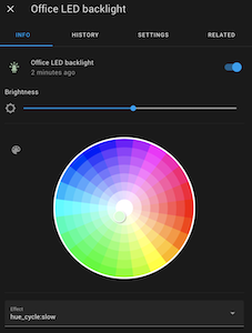
The project supports Home Assistant MQTT Discovery. After it's connected to your MQTT broker it will publish a self-identifying message to the homeassistant topic under the light category.
The default discovery MQTT prefix is homeassistant/light/ and can be changed in config_iot.h.
If you don't have MQTT discovery enabled, manual configuration is as follows.
- Add the following to your
configuration.yaml:
mqtt:
  light:
    - schema: json
      name: LED light
      unique_id: picow_ledcontrol1
      state_topic: 'picow/ledcontrol'
      command_topic: 'picow/ledcontrol/set'
      brightness: true
      brightness_scale: 100
      color_mode: true
      supported_color_modes: ["hs"]
      effect: true
      effect_list:
        - 'hue_cycle:stopped'
        - 'hue_cycle:superslow'
        - 'hue_cycle:slow'
        - 'hue_cycle:medium'
        - 'hue_cycle:fast'
        - 'white_chase:stopped'
        - 'white_chase:superslow'
        - 'white_chase:slow'
        - 'white_chase:medium'
        - 'white_chase:fast'
      icon: 'mdi:led-strip-variant'
      optimistic: false
MQTT_ADD_BOARD_ID_TO_TOPIC is enabled by default (in config_iot.h) so the final topic name will be different from the example above. To find out what it is, see troubleshooting.
If using multiple Pico Ws using this code, you should:
- Change
unique_idto a unique value - Either define
MQTT_ADD_BOARD_ID_TO_TOPICinconfig_iot.h(on by default), or set different names forMQTT_TOPIC_PREFIX(or both). Updatestate_topicandcommand_topicinconfiguration.yamlaccordingly. - Let me know if I missed something by opening an issue ;-)
cd build
make ledcontrolHold down the BOOTSEL button on the Pico and plug it into your computer. The Pico will appear as a USB drive called RPI-RP2. Copy the ledcontrol.uf2 file to the root of the drive.
for macOS Ventura, try:
cd build
/bin/cp -X ledcontrol.uf2 /Volumes/RPI-RP2/Connect the Pico to the USB and use a terminal emulator (I use screen which might not be the friendliest...) to connect to the Pico's serial port and follow the messages.
