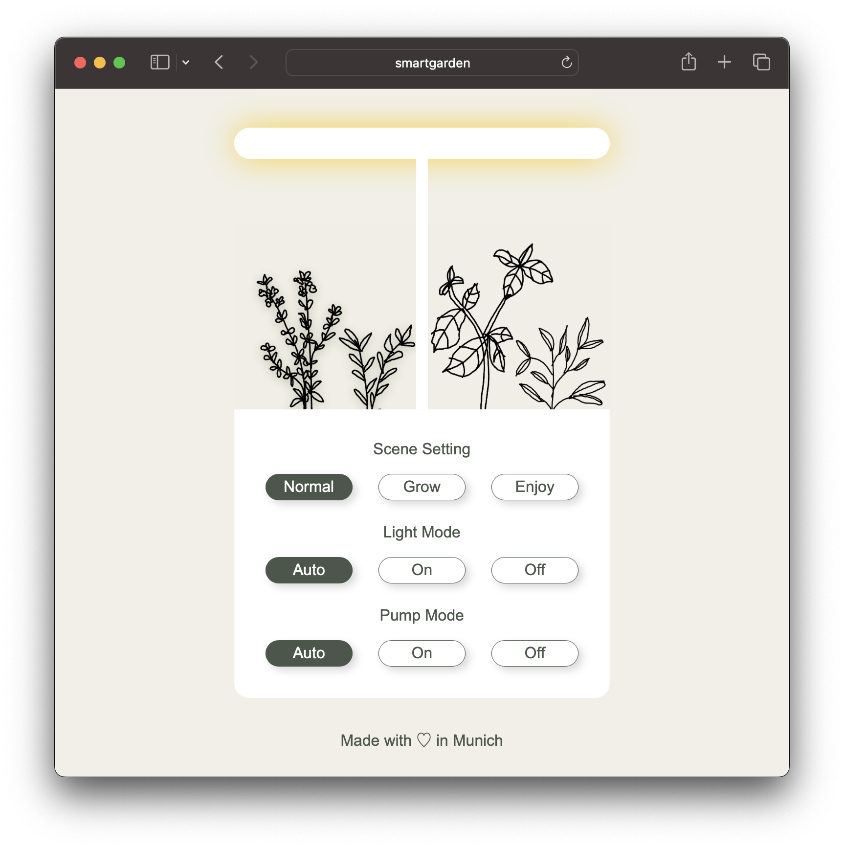
Controller and web UI for a modified IDOO hydroponic growing system using an ESP8266 microcontroller.
IDOO's hydroponic systems are controlled using on-device buttons. This project replaces all circuit boards with an ESP8266 microcontroller plus some additional electronics to control LEDs and pump.
This allows for remote control via a web UI and custom LED and pump settings. In addition, this project could easily be extended using sensors, for example to check water or nutrition levels.
That said, the main motivation for this modification was that the original IDOO circuit boards suffered from water damage, thus bricking the system.
The web UI is written in HTML and CSS. A custom
parser then turns HTML into C code (essentially a series of
Serial.println statements). The parser replaces some HTML elements with
dedicated function calls to render dynamic states (e.g., for toggles). It also points the
stylesheet link to an external host (configured in package.json).
The scenes (normal, grow, enjoy) replicate IDOO's original light and timing settings (but are based on absolute clock times). If light mode is set to auto, these timing settings are used. If set to on or off, lights are permanently on or off. The pump turns on and off every 30 minutes if set to auto.
- Upload css and images folders to a public host
- Set
hostaccordingly in package.json (e.g., "https://my.cdn.com/files") - Run
npm install - Run
npm run maketo generate C code that renders HTML
- Download and install the Ardunio IDE
- Edit sketch file
- Set Wifi
ssidandpassword - Set pins (
PIN_LED_RED,PIN_LED_BlUE,PIN_PUMP) - Put generated C code from output/html-doc.c at the bottom of the sketch
- Set Wifi
- Upload to microcontroller
- Open Arduino IDE's serial monitor
- Retrieve IP address and open in browser (e.g., http://192.168.1.68)
All components but the two original circuit boards (one in the base unit and one in the lamp shade) are re-used—in particular LEDs, pump, power adapter, and some of the wiring. Note that the top-buttons are non-functional after the modification.
This setup is in parts still a bit crude, but it works. It uses the original 24V power supply and a DC-DC converter to power the ESP8266. Three MOSFETs (IRLZ 44N) control LEDs (two colors: red and blue) and pump. Using a standard Ethernet cable between the main module and the custom connector allows for some flexibility.

