C64 living in a Gowin GW2AR FPGA on a Sipeed Tang Nano 20k with HDMI Video and Audio Output.
It has also been ported to the Sipeed Tang Primer 25K (except retro D9 Joystick, Dualshock, Paddle and MIDI support).
Original C64 core by Peter Wendrich
Dram controller and BL616 MCU µC firmware by Till Harbaum
c1541 by https://github.com/darfpga
Features:
- PAL 800x576p@50Hz or NTSC 800x480p@60Hz HDMI Video and Audio Output
- USB Keyboard via Sipeed M0S Dock BL616 µC (future plan Tang onboard BL616 µC)
- USB Joystick via µC
- USB Mouse via µC as c1351 Mouse emulation
- legacy D9 Joystick (Atari / Commodore digital type) MiSTeryNano shield
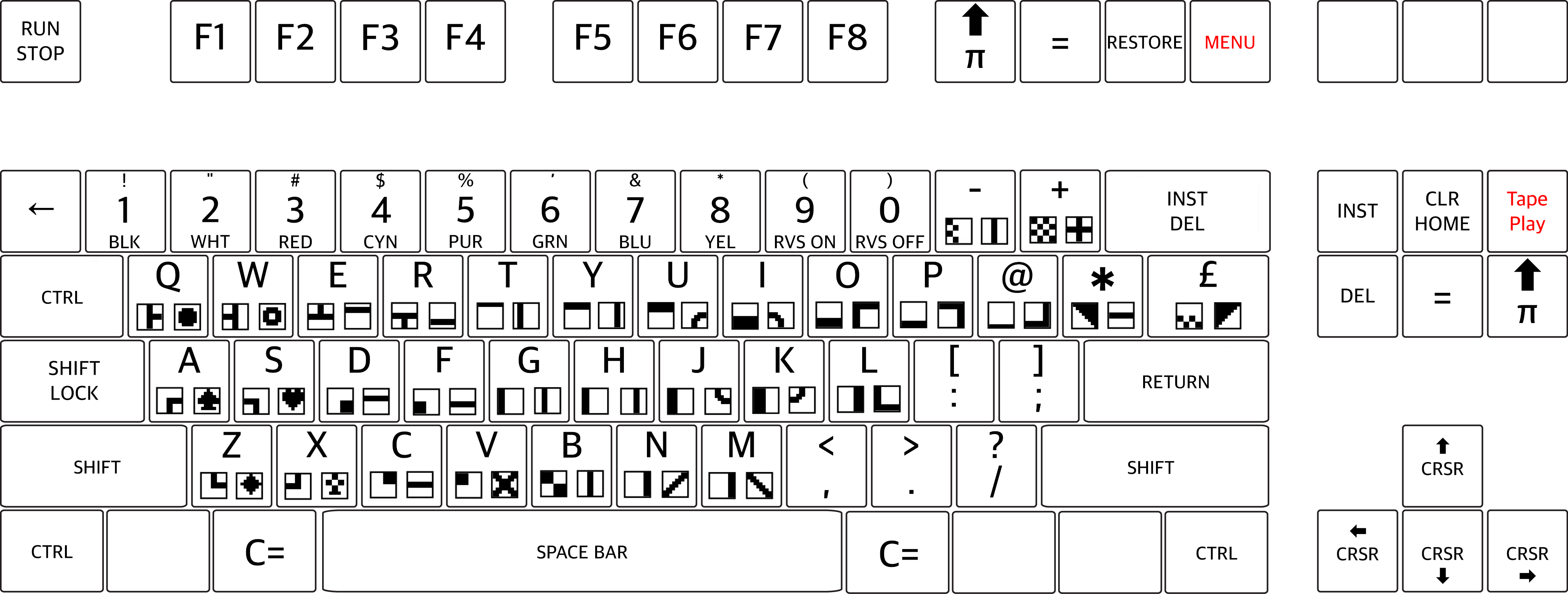
- Joystick emulation on Keyboard Numpad
- Dualshock 2 Controller Gamepad Keys & Stick as Joystick
- Dualshock 2 Controller Gamepad Sticks as Paddle Emulation (analog mode)
- emulated 1541 Diskdrive on FAT/extFAT microSD card with parallel bus Speedloader Dolphin DOS 2. GER manual
- emulated RAM Expansion Unit (REU)
- c1541 DOS ROM selection
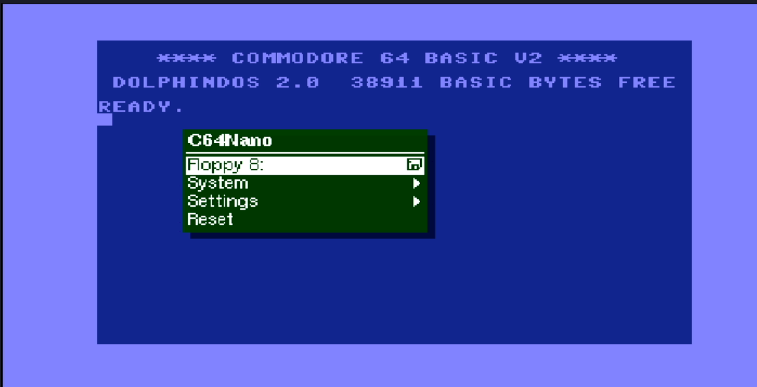
- On Screen Display (OSD) for configuration and D64 / G64 image selection
- Physical MIDI-IN and OUT MiSTeryNano shield
HID interfaces aligned in pinmap and control to match MiSTeryNano project's bl616 misterynano_fw.
Basically BL616 µC acts as USB host for USB devices and as an OSD controller using a SPI communication protocol.
Note PROJECT IS STILL WORK IN PROGRESS
The installation of C64 Nano on the Tang Nano 20k board can be done using a Linux PC or a Windows PC
Instruction.
In a nutshell memory layout of the SPI Flash:
0x000000 FPGA bitstream
0x100000 reserved for Atari ST/STE
0x200000 c1541 Dolphin DOS 2
0x208000 c1541 CBM DOS 2.6
0x210000 c1541 Speed DOS Plus
0x218000 c1541 Jiffy DOS
See Tang Primer 25K
Emulated 1541 on a regular FAT/exFAT formatted microSD card including parallel bus Speedloader Dolphin DOS.
Copy a D64 Disk image to your sdcard and rename it to disk8.d64 as default boot image.
Add further D64 or G64 images as you like and insert card in TN slot. Power Cycle TN. LED 0 acts as Drive activity indicator.
Disk directory listing: (or F7 keypress)
LOAD"$",8
LIST
Load first program from Disk: (or just LOAD)
LOAD"*",8
RUN
c1541 DOS ROM to be selected from OSD (default Dolphin DOS, CBM DOS or other)
In case a PRG don't load correctly select via OSD the factory default CBM DOS an give it a try.
For those programs the require a RAM Expansion Unit (REU) it can be activated by OSD on demand.
Playing Sonic the Hedgehog V1.2
Enable REU, and load the PRG.
Playing around with GEOS
Enable REU, select c1541 CBM DOS ROM and load the PRG.
- S2 Reset (for Flasher)
- S1 reserved
invoke by F12 keypress
- Reset
- Cold Reset + memory scrubbing
- Audio Volume + / -
- Scanlines effect %
- Widescreen activation
- HID device selection for Joystick Port 1 and Port 2
- REU activation
- Audio Filter
- c1541 Drive disk image selection
- c1541 Disk write protetcion
- c1541 Reset
- c1541 DOS ROM selection
- MIDI configuration
- Pause when OSD open
- PAL / NTSC Video mode
legacy single D9 Digital Joystick. OSD: Retro
or
USB Joystick(s). OSD: USB #1 or USB #2
or
Gamepad. OSD: DualShock
stick digital for Move and Left L1 or Right R1 shoulder Button for Trigger or following Pad controls:
| Buttons | - | - |
|---|---|---|
| Left L1/R1 Trigger |
triangle button Up |
. |
| square button Left |
- | circle button Right |
| - | cross button Down |
- |
or Keyboard Numpad. OSD: NP
| 0 Trigger |
8 Up |
- |
| 4 Left |
- | 6 Right |
| - | 2 Down |
- |
or Mouse. OSD: Mouse
USB Mouse as c1351 Mouse emulation.
or Paddle. OSD: Paddle
Dualshock 2 Sticks in analog mode as VC-1312 Paddle emulation.
Left L1 / L2 and Right R1 / R2 shoulder Button as Trigger
You have first to set the DS2 Sticks into analog mode by pressing the DS2 ANALOG button. Mode indicated by red light indicator.
Configure DIGITAL mode (press ANALOG button again) when using the Joystick mode agin. OSD: DS2
0 c1541 Drive activity. Solid 'red' after power-up indicates a missing DOS in Flash
1 unused
2 unused
3 M0S Dock detect
4 System LED 0
5 System LED 1
Multicolor RGB LED
- green all fine and ready to go
- red something wrong with SDcard / default boot image
- blue µC firmware detected valid FPGA core
- white -
Type of MIDI interface can be selected from OSD.
There is support for Sequential Inc., Passport/Sentech, DATEL/SIEL/JMS/C-LAB and Namesoft
You can use a MiSTeryNano MIDI shield to interface to a Keyboard.
Prototype circuit with Keyboard can be powered by Tang USB-C connector from PC or a Power Supply Adapter.
Source code can be synthesized, fitted and programmed with GOWIN IDE Windows or Linux.
see pin configuration in .cst configuration file
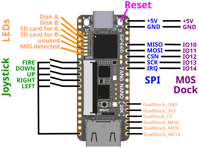
Pinmap TN20k Interfaces
Sipeed M0S Dock, digital Joystick D9 and DualShock Gamepad connection.
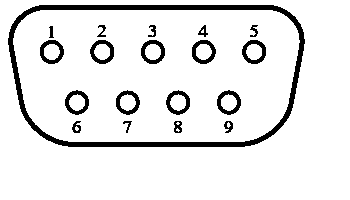
Pinmap D-SUB 9 Joystick Interface
| Joystick pin | Tang Nano pin | FPGA pin | Joystick Function |
|---|---|---|---|
| 1 | J6 9 | 28 | Joy3 RIGHT |
| 2 | J6 11 | 25 | Joy2 LEFT |
| 3 | J6 10 | 26 | Joy1 DOWN |
| 4 | J5 12 | 29 | Joy0 UP |
| 5 | - | - | POT Y |
| 6 | J5 8 | 27 | FIRE B. |
| 7 | n.c | n.c | 5V |
| 8 | J5 20 | - | GND |
| 9 | - | - | POT X |
Pinmap Dualshock 2 Controller Interface
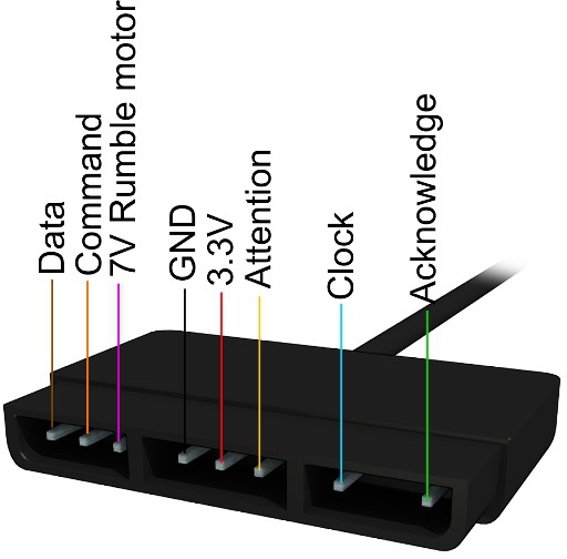
| DS pin | Tang Nano pin | FPGA pin | DS Function |
|---|---|---|---|
| 1 | J5 18 | 71 MISO | JOYDAT |
| 2 | J5 19 | 53 MOSI | JOYCMD |
| 3 | n.c. | - | 7V5 |
| 4 | J5 15 | - | GND |
| 5 | J5 16 | - | 3V3 |
| 6 | J5 17 | 72 CS | JOYATN |
| 7 | J5 20 | 52 MCLK | JOYCLK |
| 8 | n.c. | - | JOYIRQ |
| 9 | n.c. | - | JOYACK |
In order to use this Design the following things are needed:
Sipeed Tang Nano 20k
Sipeed M0S Dock
microSD or microSDHC card FAT/exFAT formatted
TFT Monitor with HDMI Input and Speaker
| HID and Gamecontrol Hardware option | needs | alternative option | Primer 25k |
|---|---|---|---|
| USB Keyboard | USB-C to USB-A adapter | 4 port mini USB hub | x |
| USB Joystick(s) | 4 port mini USB hub | - | x |
| USB Mouse | 4 port mini USB hub | - | x |
| Commodore/Atari compatible retro D9 Joystick | MiSTeryNano shield | D-SUB 9 M connector, breadboard to wire everything up, some jumper wires | - |
| Dualshock 2 Controller Gamepad | Gamepad Adapter Board (Sipeed Joystick to DIP) | breadboard to wire everything up and some jumper wires | - |
