- 1. About this document
- 2. Starting point
- 3. Step 1 - First prototype
- 4. Step 2 - Attach a button to trigger a stage
- 5. Step 3 - bring things together to see how the loop runs with buttons
- 6. Step 4 - rotary encoders
- Appendix A: Requirements
- Appendix B: Interface design thoughts
- Appendix C: 3d printed test stand
- Appendix D: openscad library for custom keycaps
A project to add some more control to the PS5 Kerbal simulation.
After installing Kerbal on the PS5 and playing it for a while it quickly became clear that the controllers alone are not enough to enjoy the game. The search began to find some way of improving things. Kerbal allows control via the PS5 controllers AND via keyboard and mouse. This means it should be possible to add some easy toggles/ switches/ rotary encoders to pass information to the game. The first switch would be the space bar which kerbal uses to trigger stages.
While this is being developed for Kerbal it is generally a keyboard and can just as easily be used for many other applications, including video conferences.
The following is a list of key bindings we can work with.
The first key will be the space key to launch rockets.
Initial choice for a prototype is the AVR ATmega32u4 8-bit microcontroller which has a USB controller and can be used as both a keyboard and mouse if required.
The Pro Micro is an Arduino-compatible microcontroller board developed under an open hardware license by Sparkfun. Clones of the Pro Micro are often used as a lower-cost alternative to a Teensy 2.0 as a basis for a DIY keyboard controller/converter when a lower number of pins would suffice.
Because it’s always good to have status LEDs and the WS2812 is both easy to get and has good libraries, with fastled and adafruit, it’s the first choice.
The fastled library looks like a good choice. The WS2812 LED rings I have are not tightly packed with LEDs but will suffice. As I have a few WS2812 strips and a few WS2812 rings the choice went towards the WS2812 to be able to mix the strip and ring. In a first test I had accidentally used an RGBW ring which showed up that the fastled library can’t handle them well so WS2812 is the choice now.
To get started I went to an example for LEDs to be able to later set a LED with a key/button.
link:./fastled-test/fastled-test.ino[role=include]|
Note
|
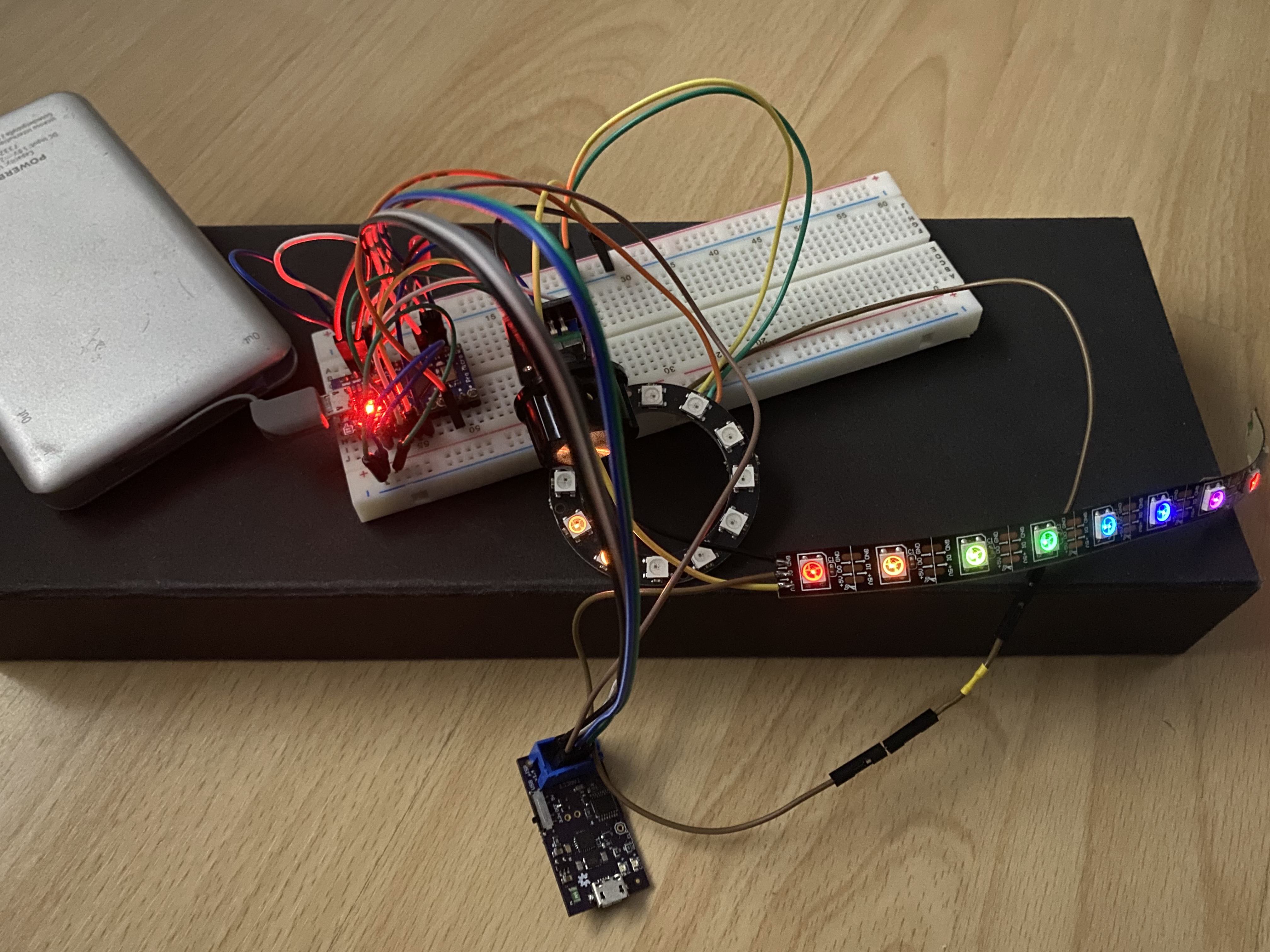
The first test looks good and was tested on a 5v pro micro. The prototype uses a strip with ten LEDs attached to a ring with 12 LEDs. |
The above code runs a LED around the ring and sets static colours on the strip. A good start. The animation works with delay which is probably not a good solution but works fine for a first test.
Since this will be starting rockets let’s make it feel that way. Just the space bar and maybe a toggle to arm it.
-
keyboard
-
Button
-
State change detection
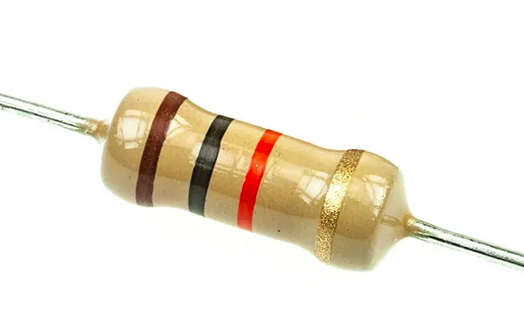
We will need to pull down/up the pin for the button so the above resistor is included to show an example 10K Ohm resistor. The pro micro may have inbuilt pull up/down resistors but that has to be checked. Pulling a line up or down endures it is always in a defined state and that it reacts quickly so that it is highly recommended even for testing.
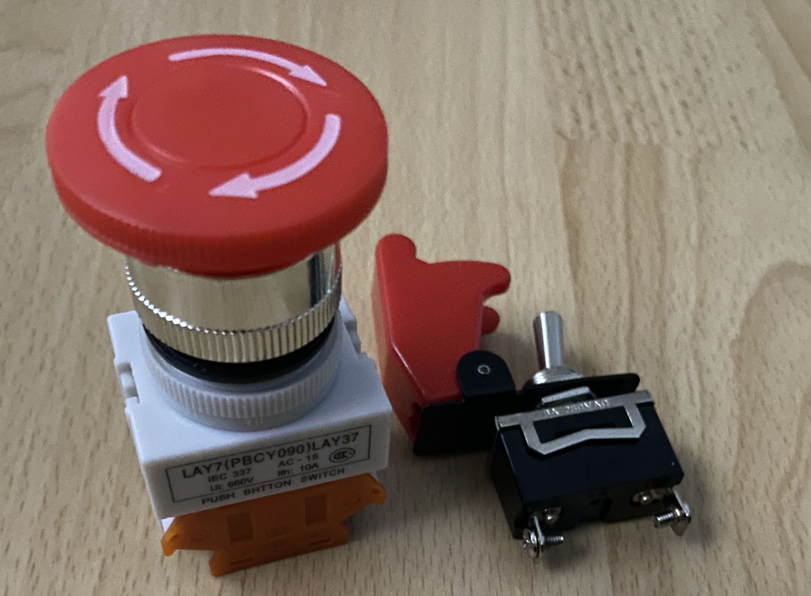
The big red button is to trigger a stage and the toggle switch is to arm it. In this case we will soft arm the bitton as opposed to disconnecting it directly.
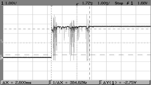
Why all the fuss about bounce? And what is it?
The Pro Micro has five external interrupts, which allow you to instantly trigger a function when a pin goes either high or low (or both). If you attach an interrupt to an interrupt-enabled pin, you’ll need to know the specific interrupt that pin triggers: pin 3 maps to interrupt 0 (INT0), pin 2 is interrupt 1 (INT1), pin 0 is interrupt 2 (INT2), pin 1 is interrupt 3 (INT3), and pin 7 is interrupt 4 (INT6).
pro micro hookup guide
void my_interrupt_handler()
{
  static unsigned long last_interrupt_time = 0;
  unsigned long interrupt_time = millis();
  // If interrupts come faster than 200ms, assume it's a bounce and ignore
  if (interrupt_time - last_interrupt_time > 200)
  {
    ... do your thing
  }
  last_interrupt_time = interrupt_time;
}
The above short section shows a debounced interrupt that uses millis instead of delays. The important thing here is that if we debounce with delays we stall the whole loop so that if we have a LED animation or something else running it get’s stalled. Using millis allows the rest to keep running.
Let’s see if some of the above works.
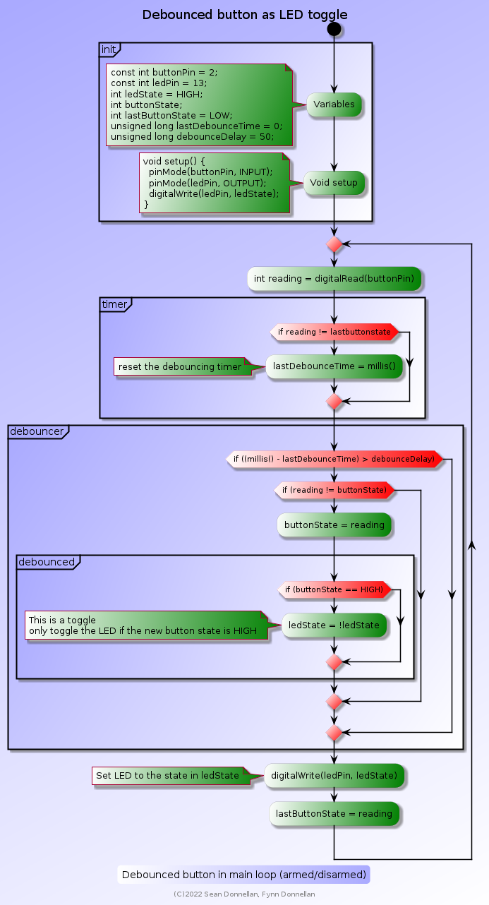
link:./button-test/button-test.ino[role=include]|
Note
|
The first test looks good and was tested on an arduino UNO. |
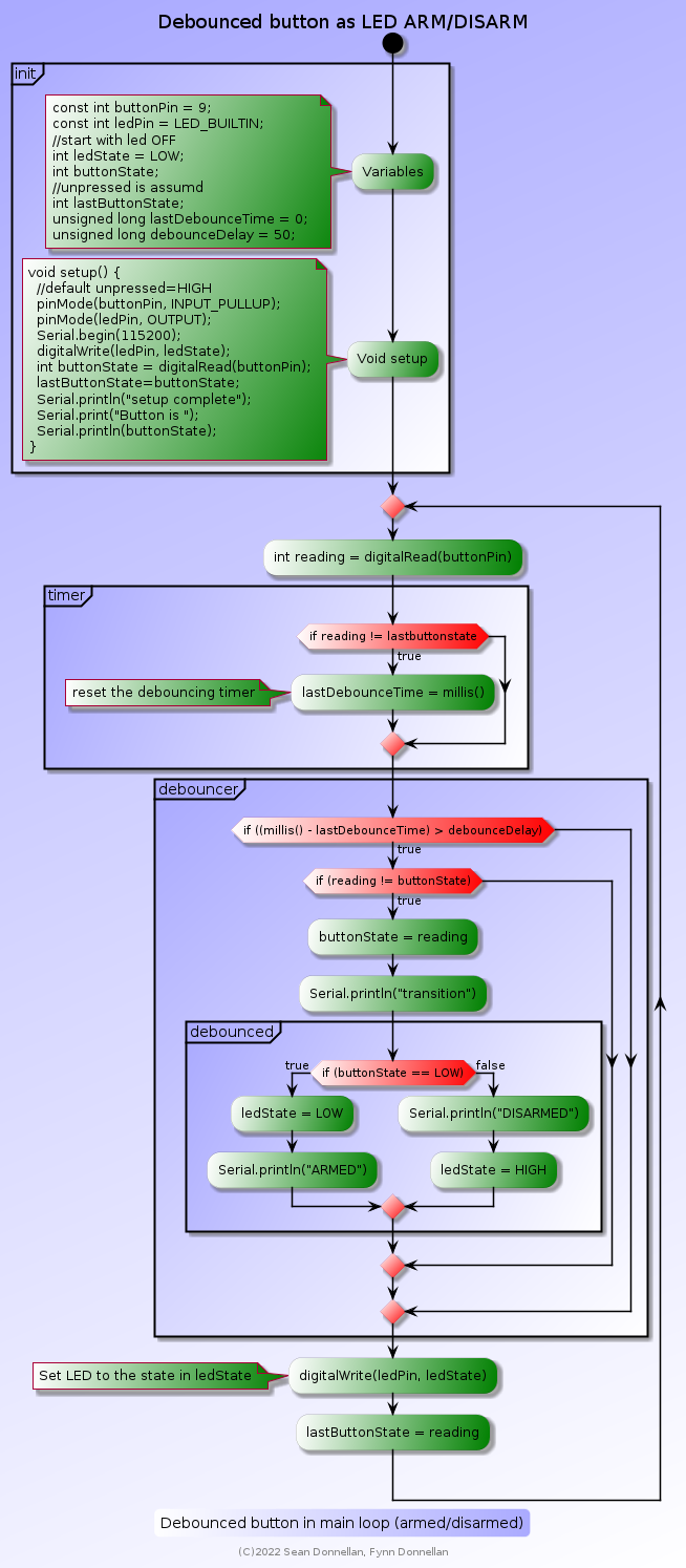
The above code works as a debounced latching button. The aim though is to read a debounced button and to read it’s state changes.
-
ONLY when the button is pressed
-
output state ONCE
-
-
When button is released
-
Output state once
-
|
Warning
|
Work in Progress |
link:./fastled-test2/fastled-test2.ino[role=include]-
Control Kerbal on PS5
-
Via USB(A) keyboard interface
-
Use big red button with latch for stages
-
-
Must show actions/button presses
-
WS2812 for key status changes red/green/etc
-
-
Add some safety toggles (arm/disarm)
-
A classic toggle with red cover
-
-
Control
-
Stage trigger (space bar)
-
SAS (on/off) (t)
-
gear (up/down) (g)
-
time warp (rotary +/-) (.,)
-
throttle (rotary +/-) (shift,cntrl)
-
motors (on/off) (x,k)
-
View (inside/outside) ???
-
-
This should cover the most required buttons and should be possible without multiplexing.
Since the first button is a big red one with a latch it make sense to also show what state it’s in. Adding a LED ring around it sounds like a good idea. Adding a LED ring around a rotary encoder also sounds like a good idea (optional).
- toggle disarmed
-
disArm led LED red(?), latch ring red blink(?)
- toggle armed
-
ARM led green, latch ring green
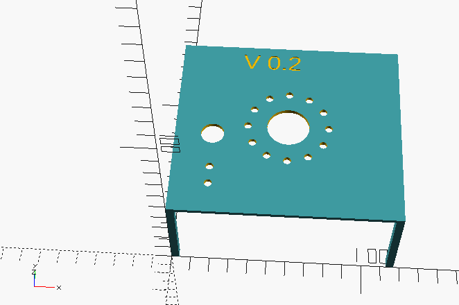
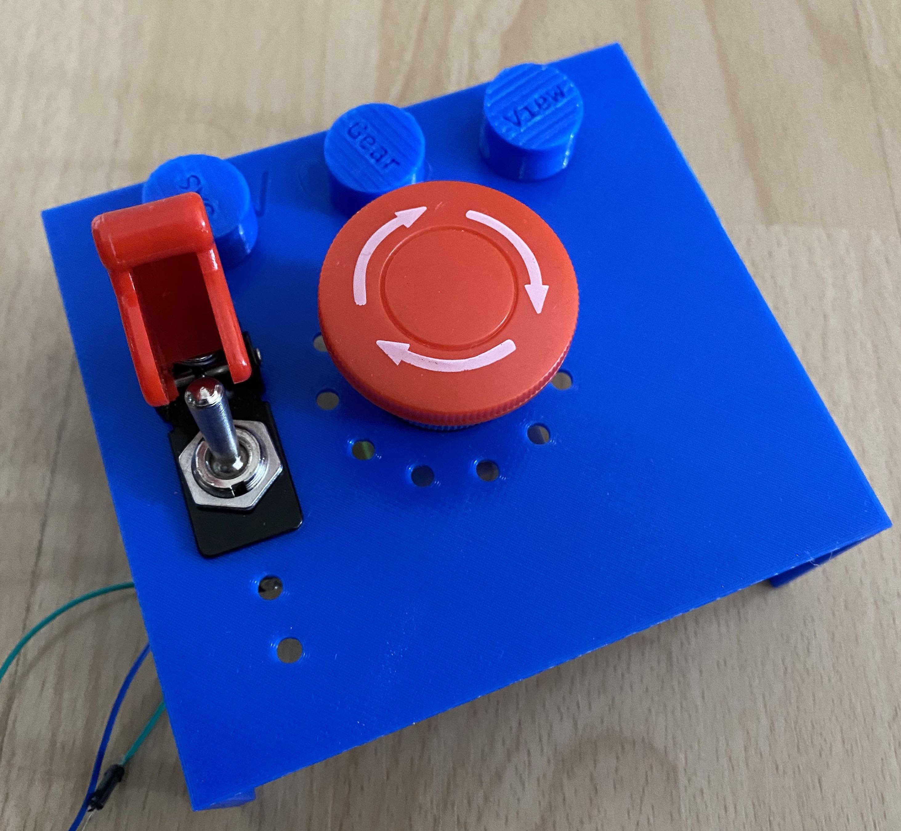
The Aim here is to have a stand to mount the buttons and LEDs to while testing. After testing this can be used as a template for drilling. Also this can later be adapted to make a holder for the led ring and potentially the LEDs that can be mounted under the lid of the box.
link:./3d/protoTypeStand.scad[role=include]The first test fitting worked well to show up some room for improvement:
-
Toggle switch moved left and down
-
legs longer
-
LED ring proper Radius
The intial V2 print populated with additional key caps placed to show approximate position of possible keys for later.
the following library allows the creation of keycaps in different sizes and shapes. since we’ll be drilling the holes for any buttons round keycaps for cherry mx switches looks like a good option for keys.
As there is a broken backlit keyboard lying around it will probably find itself devoid of some switches for this if they fit.
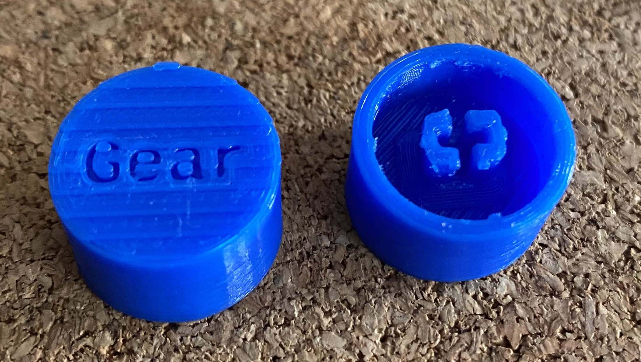
link:./3d/keycaps.patch[role=include]The above keycaps fit the MX clone switches we have and will work for prototyping. To make them look like really high quality switches some post processing will be required. This was a quick and dirty print in low resolution for initial testing.
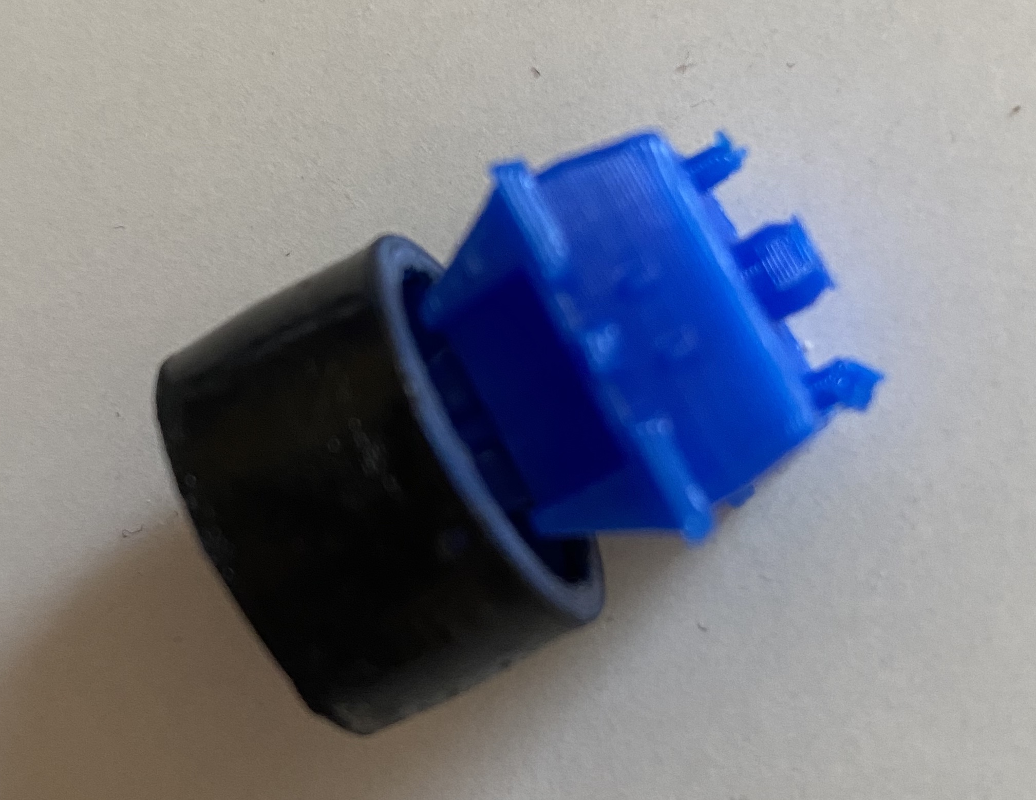
Just to be sure the above mokup key was printed and it turns out there might be a clearance problem with the switch housing. It was not as apparent when test fitting to the switch as it was between other keys.
-
One variant might be to print Caps with no inlay
-
Sand with 1000+ grit
-
Paint
-
Cover with tape
-
Laser inlay through tape
-
Paint inlay
-
Remove tape
-
-
Another variant might be to print in the target colour with inlay
-
Paint inlay
-
Sand with 1000+ grit
-
The above approaches need to be tested but since printing key caps is easy enough now this also should be easy enough. It might involve printing a positioning guide to help align any laser cutting and that can be done at a later stage if required.
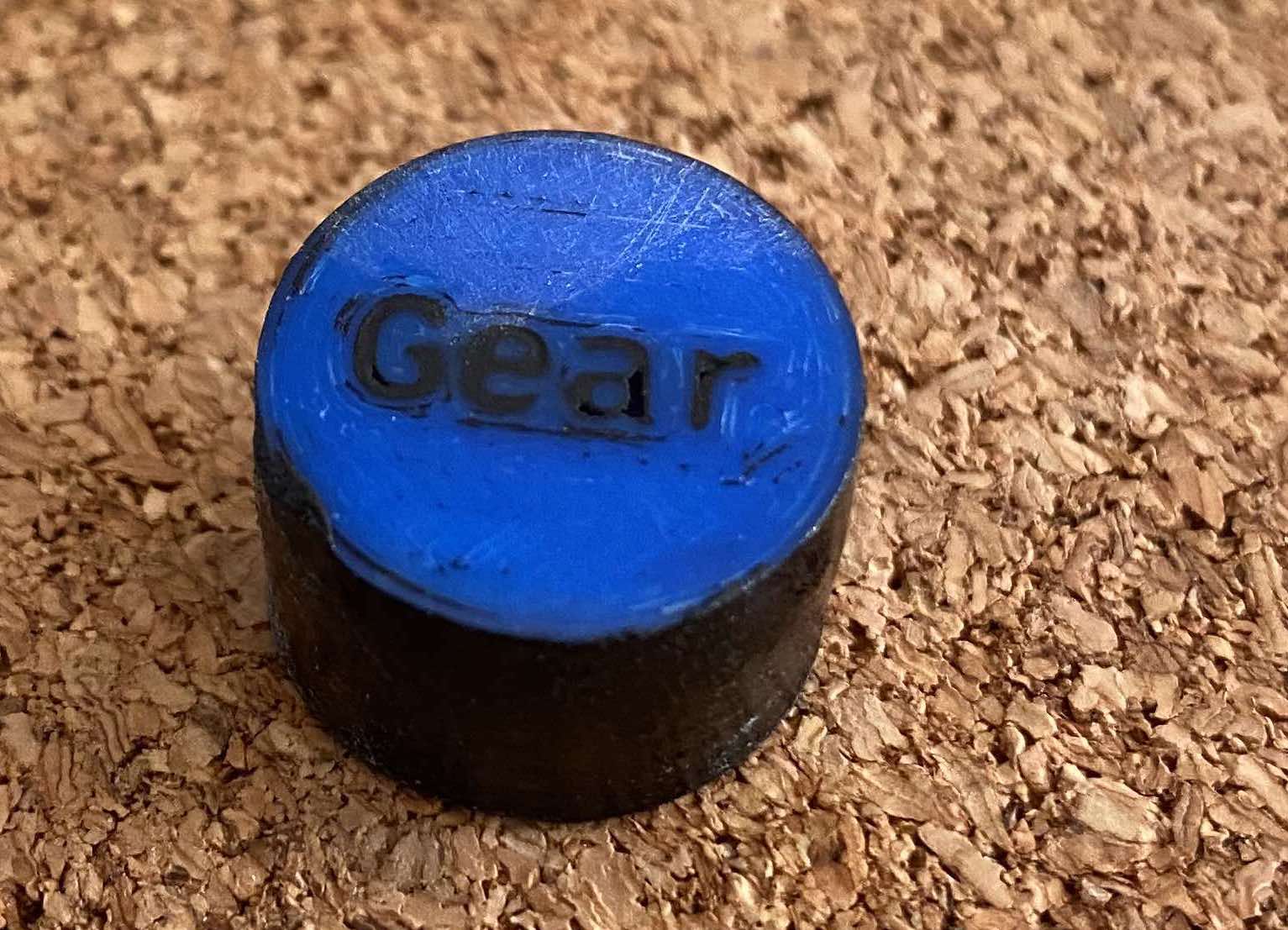
From this initial very fast test it looks like the laser option is getting more likely. Because the keycap is sloped the sanding uncovers the slope lines and, because we’re hand sanding, unevenly. This leaves a slight artefact that would ideally beg for a coat of paint which would cover the inlay again so the simple sand - paint - sand option doesn’t look that good. The painted part did look good though even if it didn’t have time to dry. One question is what will the laser do with PLA. One question though is answered: The inlay looks good and sanding works well if combined with paint.
The above macro photo shows that PLA doesn’t look that nice when sanded. There was an initial hope that heat might help smooth it again. The result of heat to the above key, while not shown, was uneven and unsatisfactory and probably requires more skill to do well so that the 2 minutes spent might have turned something better up if they had been 15 minutes. Still the result of the 2 minutes with a gas torch showed that the layer lines will be highlighted through heating so that it probably only makes good sense for a flat surface or one with finer layer lines more closely spaced. There is probably room for experiments with solvents here also as others have had success with that. The laser option looks to probably be the one with a higher degree of repeatability and probably a better surface finish also through sanding and painting and sanding and painting and then lasing through tape and filling in the inlay with the tape in place. The laser will require some help with positioning so a printed MX key stalk on a positioning plate for a wainlux K6 laser will probably be designed and printed to assist as otherwise the sloped keys are likely to be misaligned through rotation more than X/Y position. Maybe something like this: https://www.thingiverse.com/thing:4712402
As described above using a laser to engrave the keycaps might be the road to a clean look.
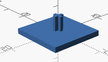
The first step is to print a cherry keycap holder.
This is a requirement to be able to position the key caps repeatably. And this would have been good for the spray painting of the first cap too (maybe a bit higher). Since the keycap is slightly slanted this holder should probably account for that (V1 doesn’t). The laser engraving should work fine none the less and if not the slant will be adapted to the holder also.
link:./3d/cherry_keycap_holder.scad[role=include]-
Print a blank keycap
-
Repeat as required:
-
Sand the keycap (1000 Grit or higher)
-
Spray paint the cap (1st coat with filler?)
-
-
Mask the cap with tape
-
Laser engrave
-
Fill inlay
-
Remove tape
-
Optionally add clear coat
