Helps to create a docker image of a LoRa Server based on ChirpStack using the Semtech protocol and the band frequency of AU915
Before you start the server theres some commands that you have to run, just copy and paste one by one the commands bellow:
git clone https://github.com/douglasJovenil/lora-server
cd lora-server/container
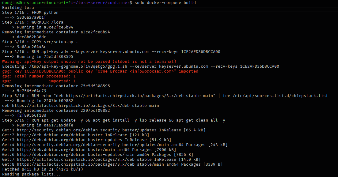
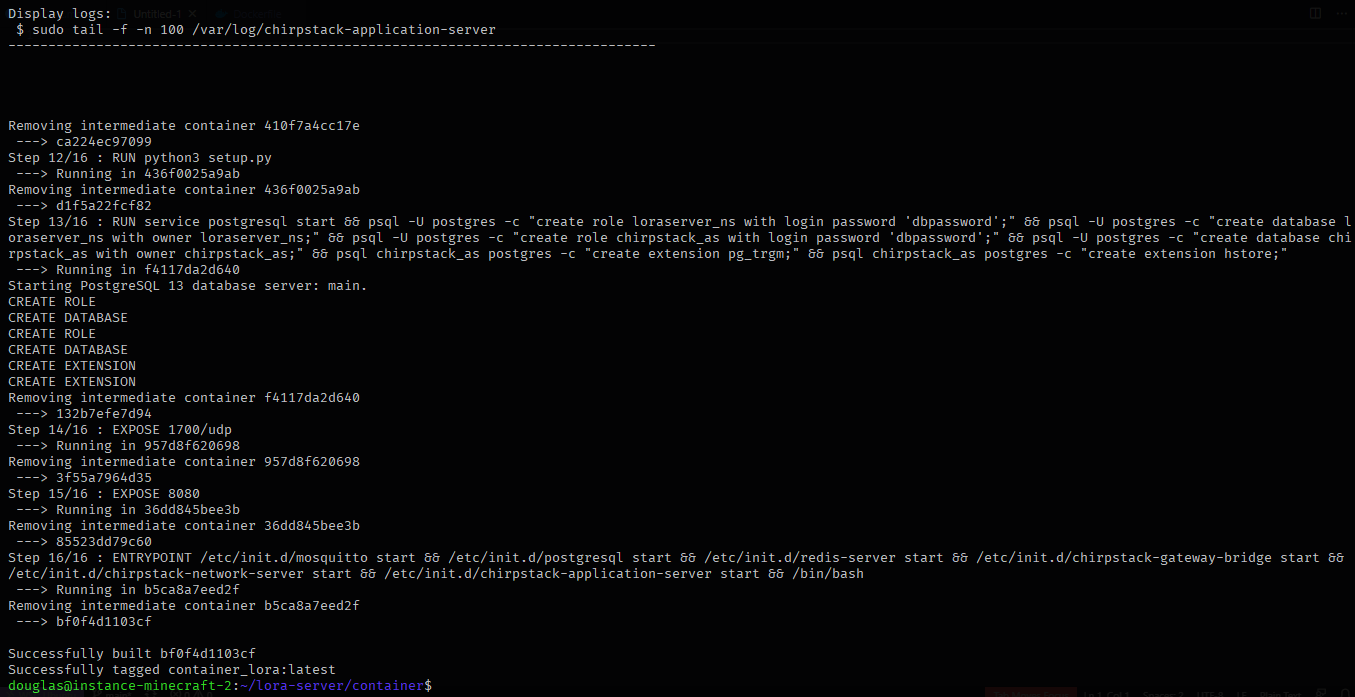
sudo docker-compose build
Now to run:
docker-compose up -d
You can also show the logs of each application:
- chirpstack-gateway-bridge
tail -f /var/log/chirpstack-gateway-bridge/chirpstack-gateway-bridge.log - chirpstack-network-server
tail -f /var/log/chirpstack-network-server/chirpstack-network-server.log - chirpstack-application-server
tail -f /var/log/chirpstack-application-server/chirpstack-application-server.log
IMPORTANT: remember to open the port 1700/udp and 8080/tcp on your firewall.
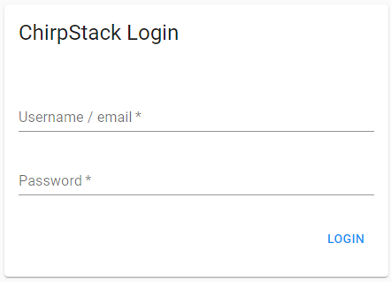
Access the address localhost:8080 on your web browser
Insert the following credentials:
- user: admin
- password: admin
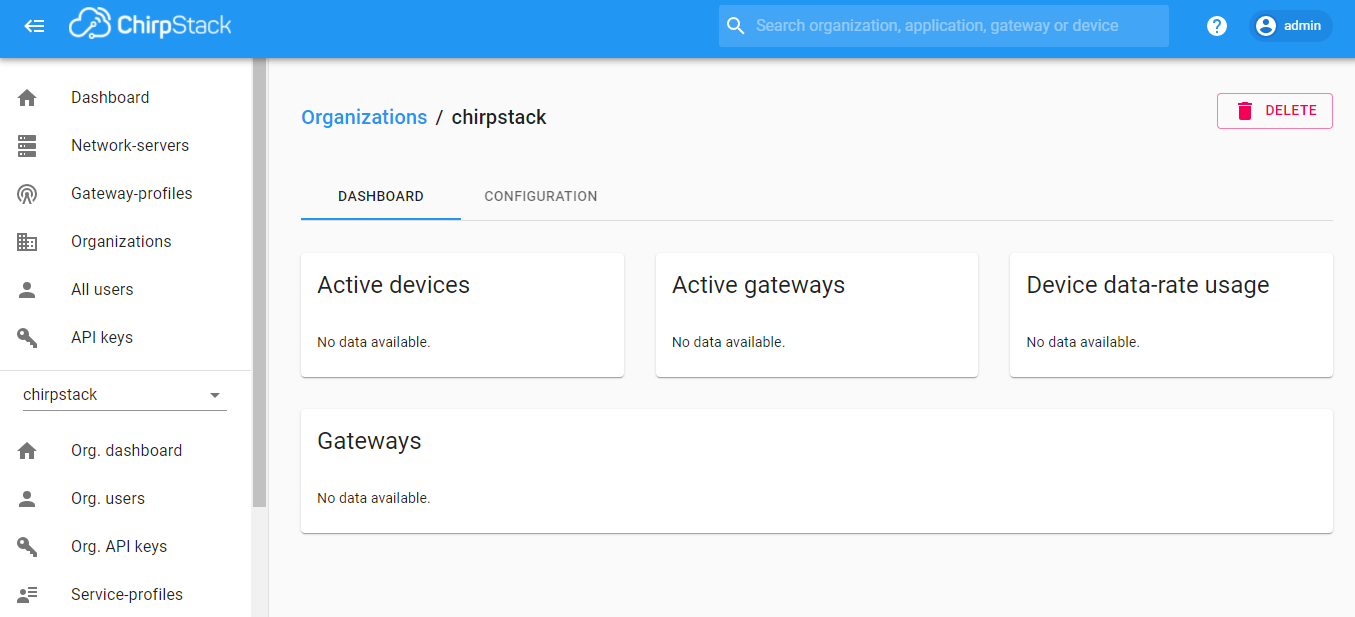
If there are no problems, you will be redirect to dashboard
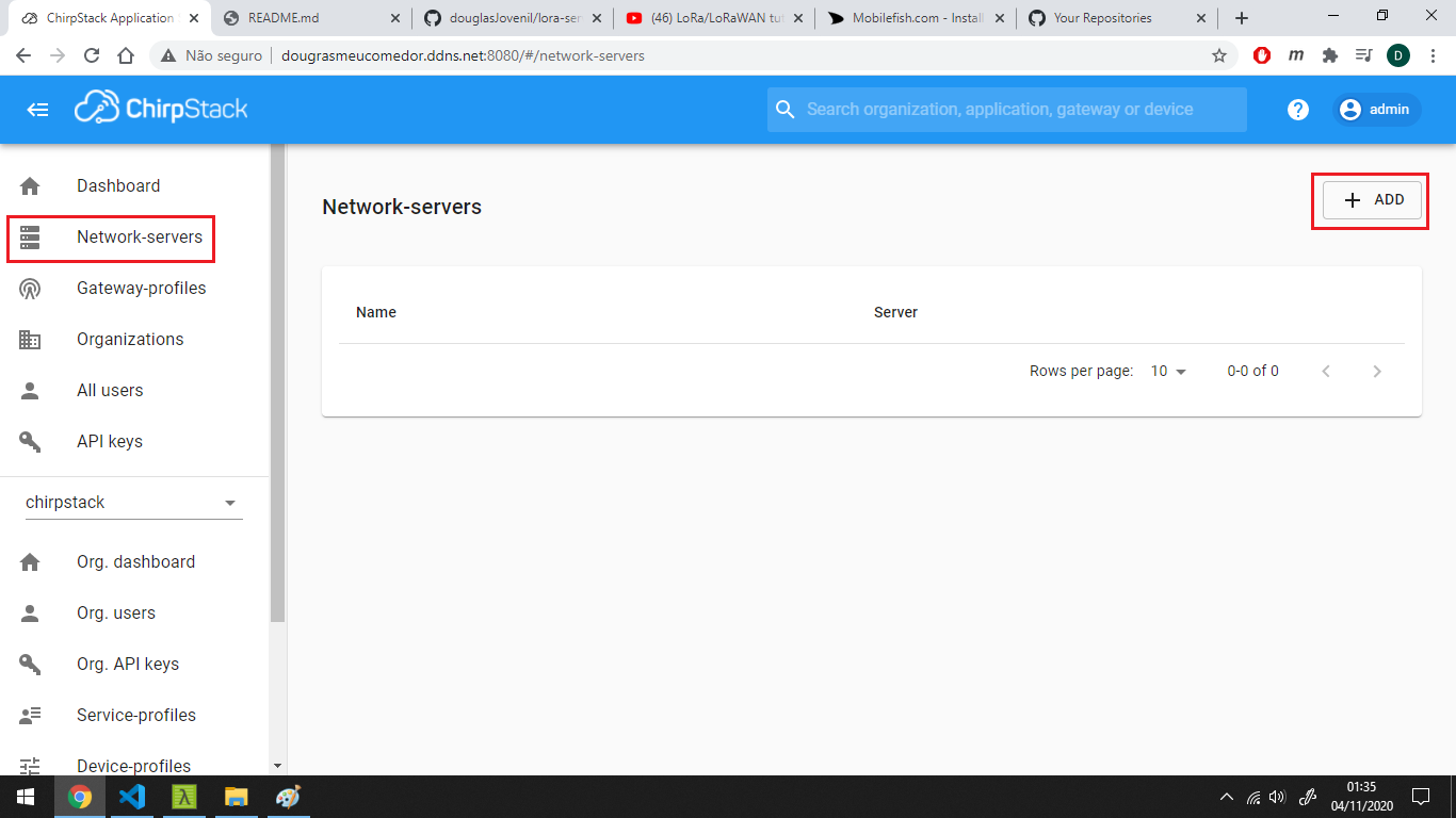
Click on Network-server then ADD
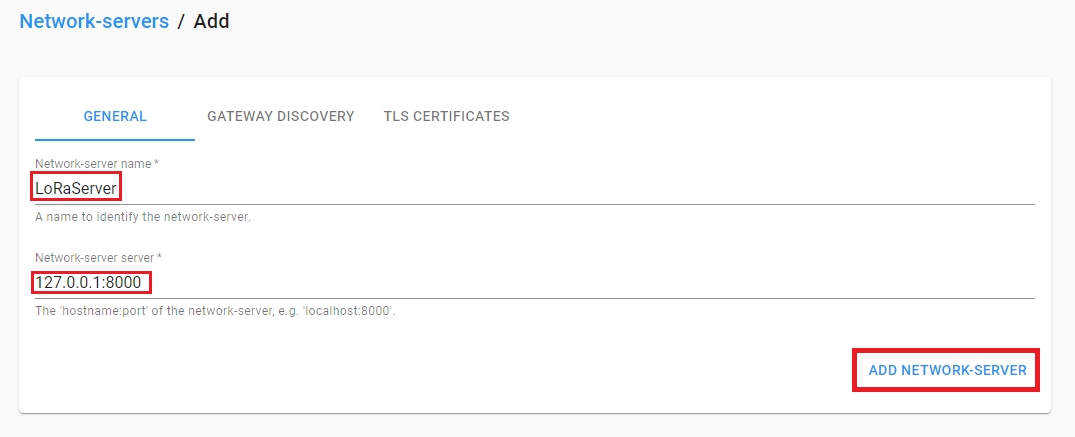
On this screen we have to fill the fields
- Network-server name: any name that you will use to identify the server
- Network-server host: the address of the machine that is running the chirpstack-network-server application, in this case this application is on same machine of chirpstack-application-server so we can just use 127.0.0.1:8000
With this field filled just click on ADD NETWORK SERVER
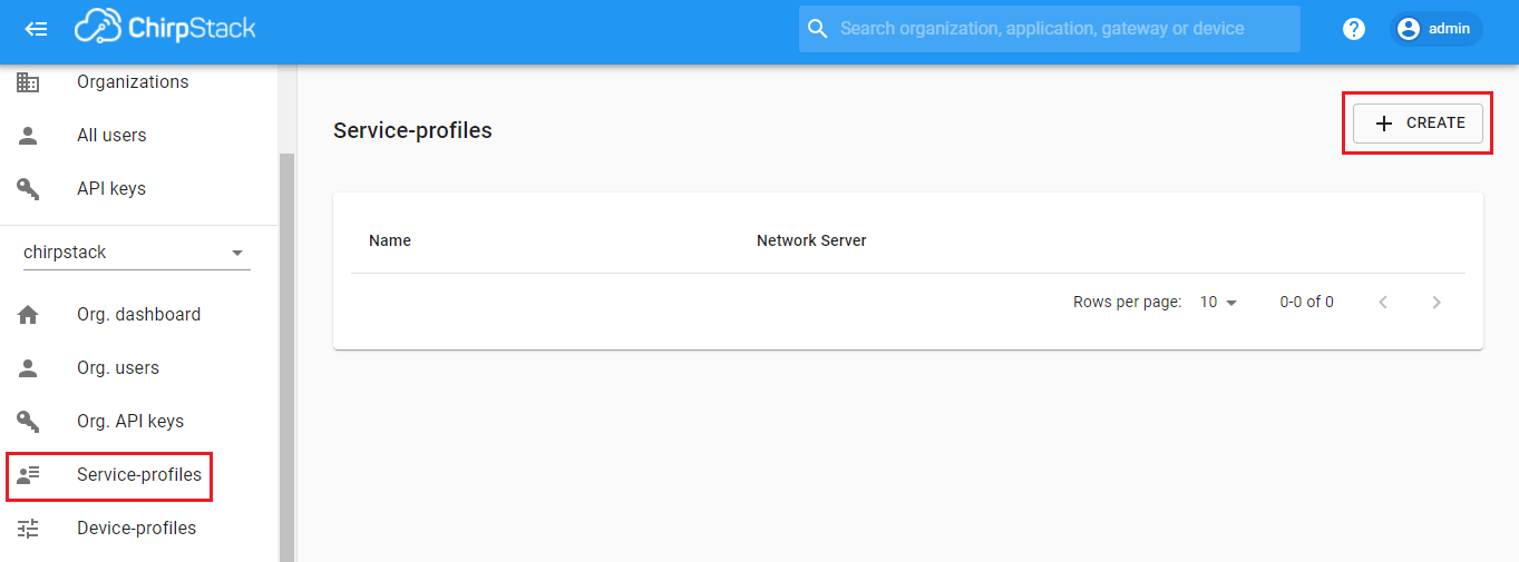
Click on Service-profiles then CREATE
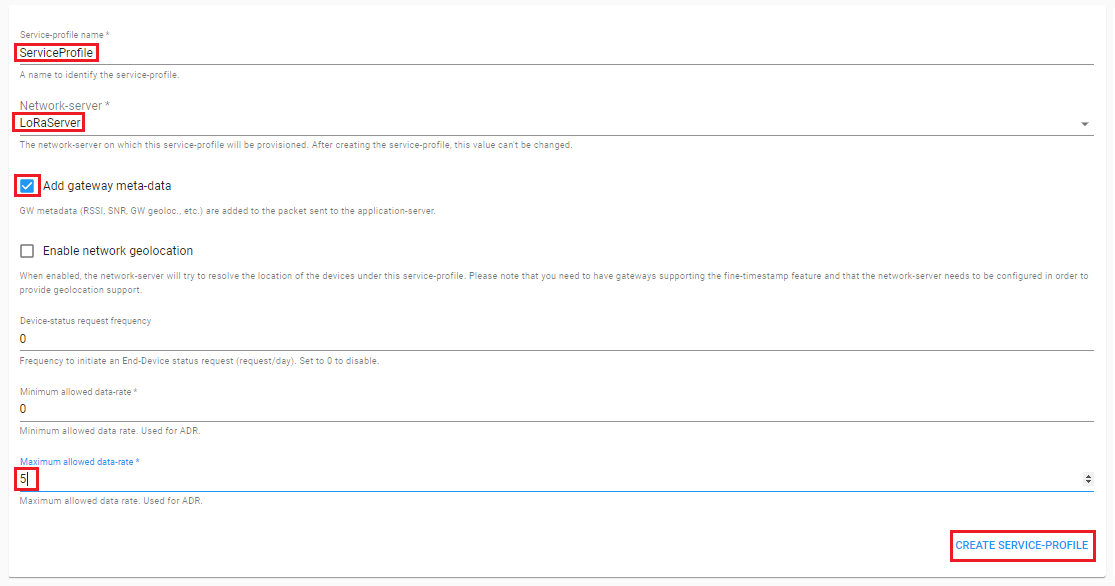
On this screen we have to fill:
- Service-profile name: any name that you will use to identify this service
- Network-server: the LoRa server that we created on previous step
- Maximum allowed data rate: This field we set to 5, this value respect the Semtech protocol
And check the field:
- Add gateway meta-data: adds information of gateway to the package
Then click on CREATE SERVICE-PROFILE
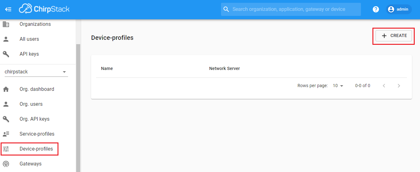
Click on Device-profiles then CREATE
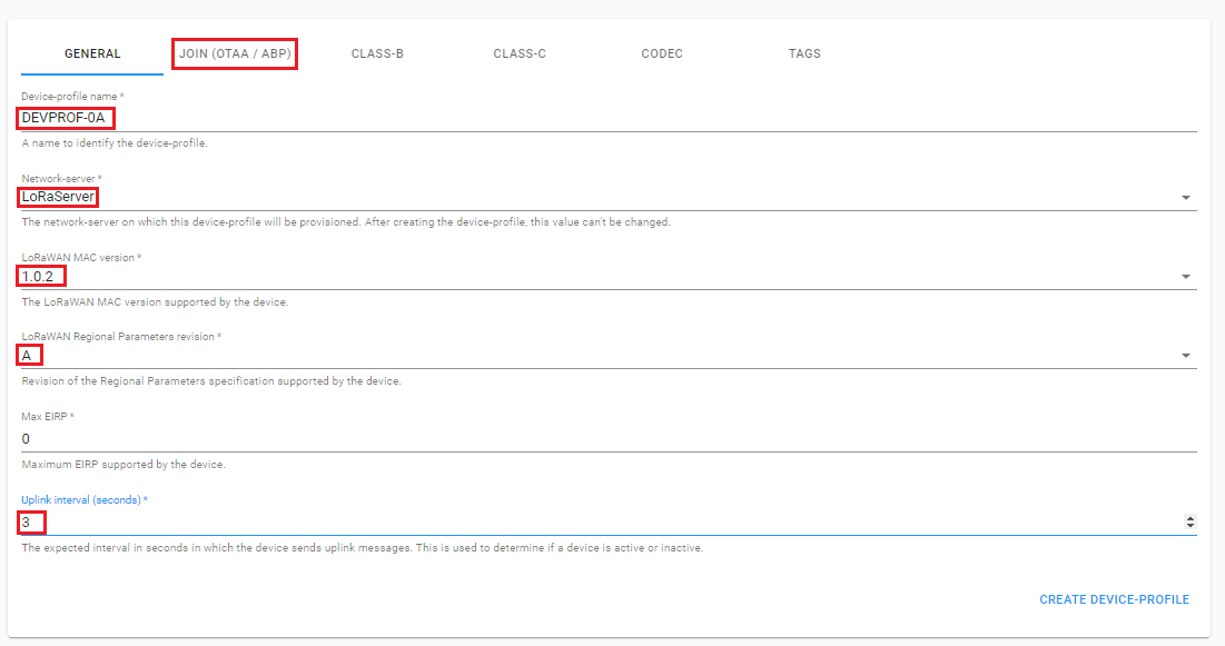
We will have to fill:
- Device-profile name: any name that you will use to identify this type of device
- Network-server: the LoRa server that we created on the first step
- LoRaWAN MAC version: if you will follow this documentation, just use 1.0.2
- LoRaWAN Regional Parameters revision: type of your LoRa device.
- Uplink interval (seconds): interval between uplinks
Then click on JOIN (OTAA/ABP)
Check the box Device support OTAA then click on CODEC
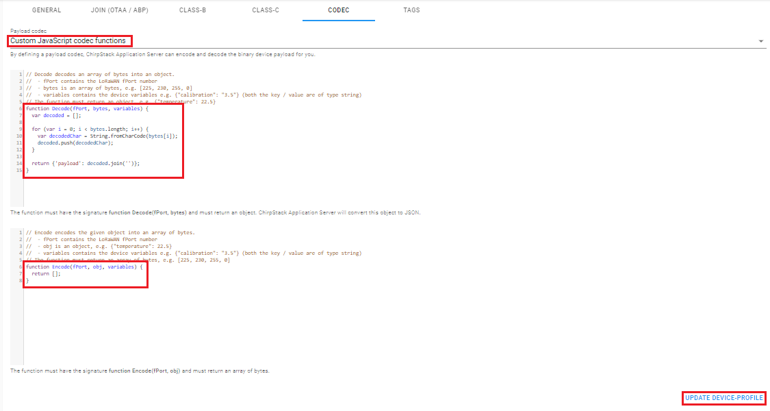
Select Custom JavaScript codec functions, with this you can just write any function that you desire to encode e decode your packages. After you write your functions, click on CREATE DEVICE-PROFILE
In this codec that I made, I just make the conversion of hex to char and then join the array, if you want do the same thing, use the following code:
function Decode(fPort, bytes, variables) {
  var decoded = [];

  for (var i = 0; i < bytes.length; i++) {
  	var decodedChar = String.fromCharCode(bytes[i]);
    decoded.push(decodedChar);
  }

  return {'payload': decoded.join('')};
}
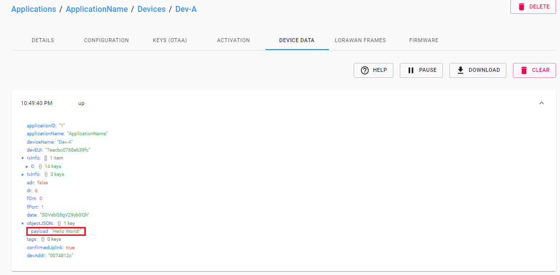
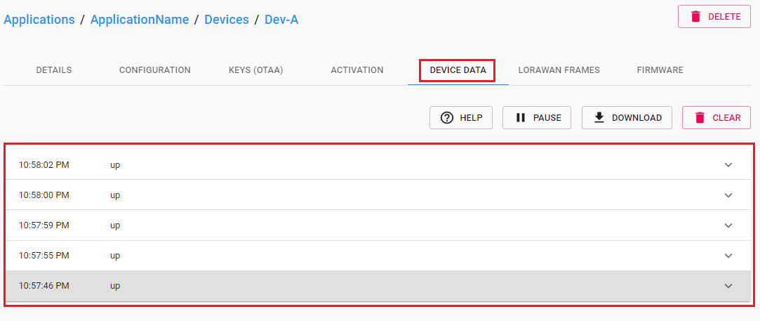
As result, you have this kind of package when observe the device data:
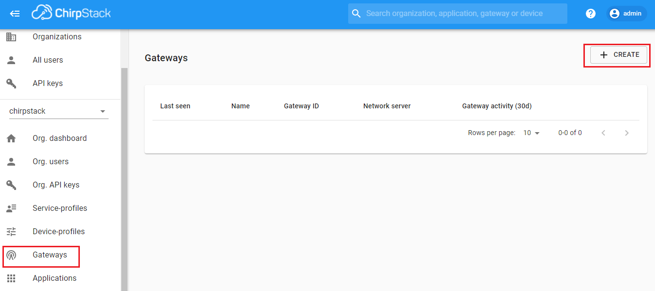
Click on Gateways then CREATE
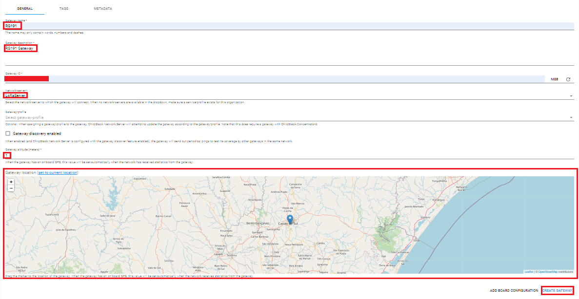
On this screen fill the fields:
- Gateway name: any name that you will use to identify this gateway
- Gateway description: any description to specify this gateway
- Gateway ID: MAC address of your gateway
- Networkserver: the LoRa server that you created on first step
- Gateway altitude (meters): any value, this will be update on first uplink
- Gateway location: local where your gateways is
Then click on CREATE GATEWAY
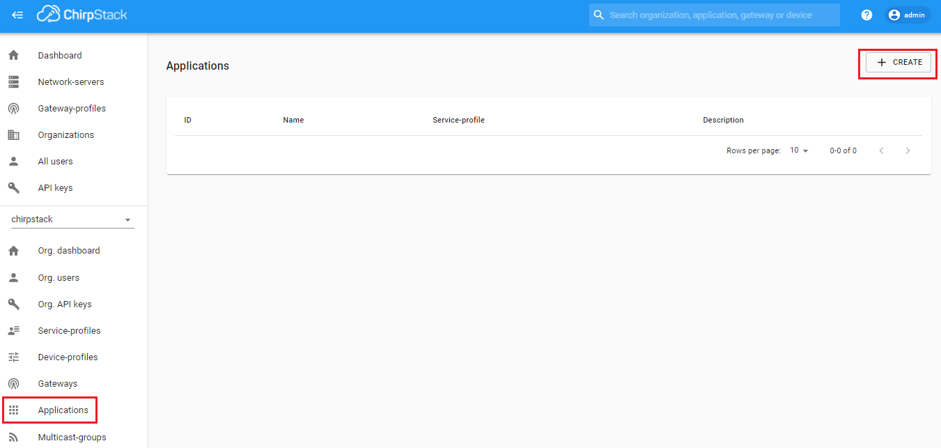
Click on Applications then CREATE
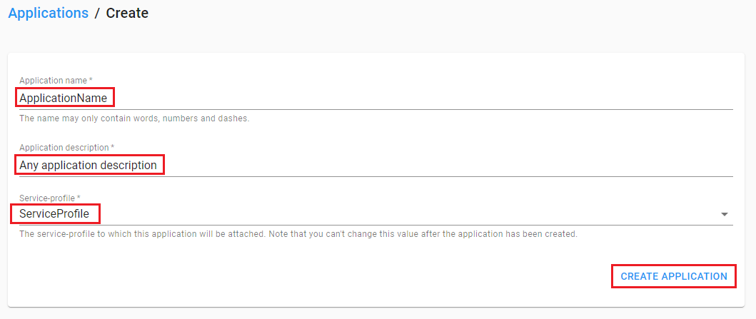
On this screen fill the fields:
- Application name: any name that you will use to identify this application
- Application description: any description to specify this application
- Service-profile: service that you created previously
then click on CREATE APPLICATION
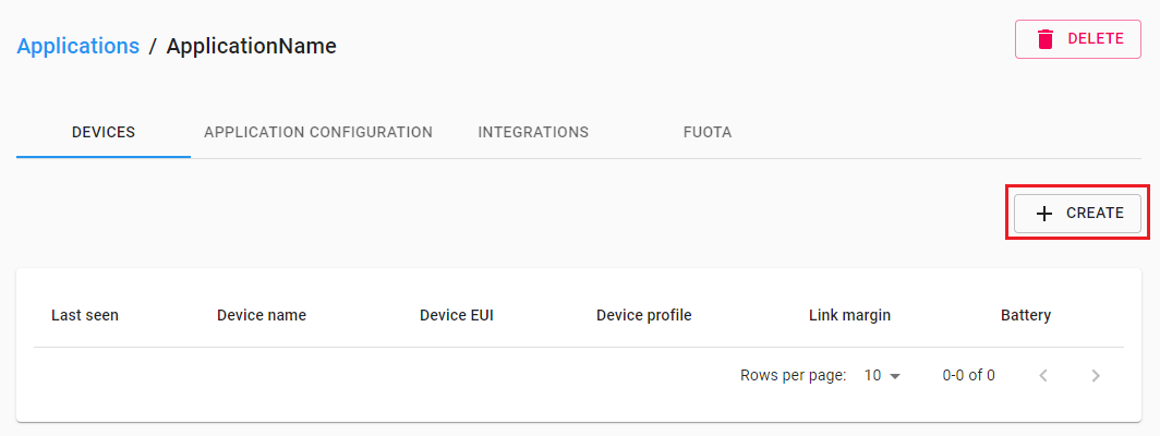
Select the application that you created on previous step
Then CREATE
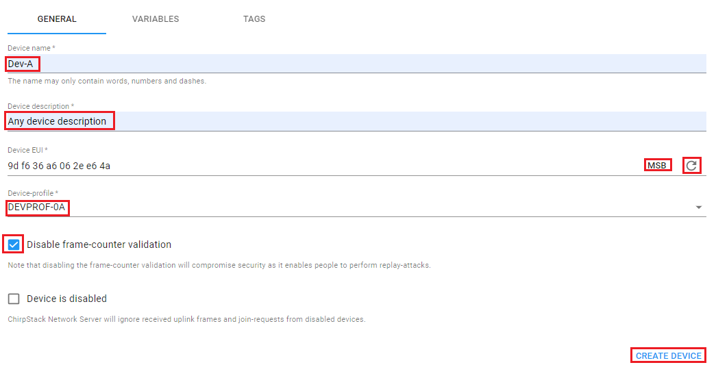
On this screen fill the fields:
- Device name: any name that you will use to identify this device
- Device description: any description to specify this device
- Device-profile: profile that you created previously
In the field Device EUI select MSB (if you will use my device library, other wise use LSB) and click on refresh icon to generate a Device EUI.
Check the following fields:
- Disable frame-counter validation: only when you are testing the device
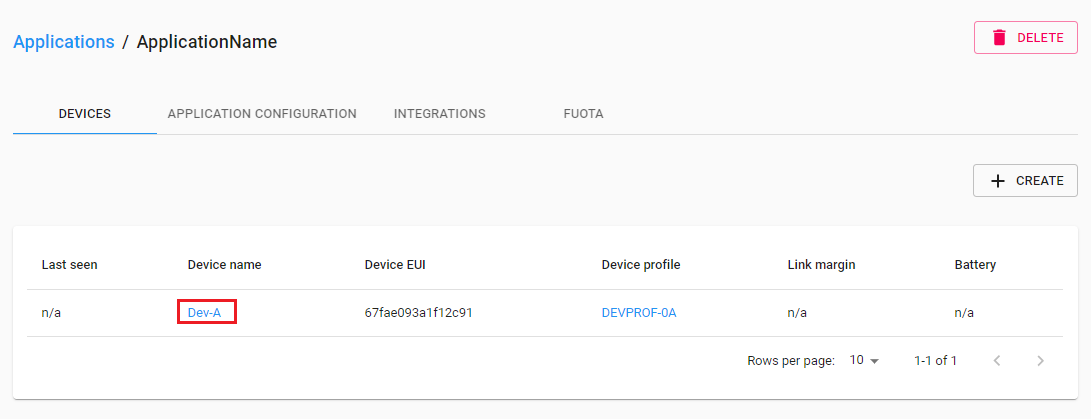
Now select the device
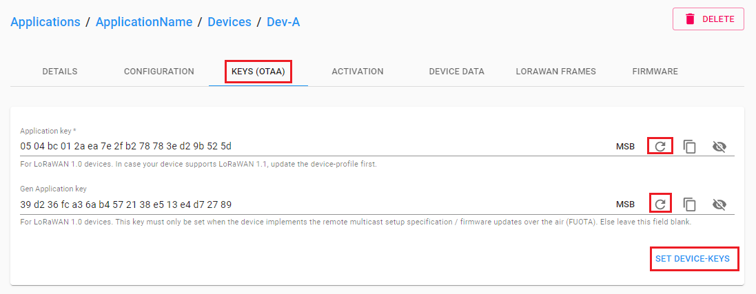
Click on Keys (OTAA), click on both refresh icons to create Application key and Gen Application Key then SET DEVICE-KEYS. You will use this keys to setup your hardware.
Your device is done, if you desire to watch the data on your device just click on DEVICE DATA
