
Galileo-IO is compatible with Intel's Galileo Generation 1, Galileo Generation 2 and Edison boards (Mini and Arduino Board, SparkFun GPIO & Arduino Blocks, Xadow Board, DFRobot Romeo & IO Expansion)
Galileo-IO is a Firmata.js-compatibility class for writing Node.js programs that run on the Intel Galileo or the Intel Edison. This project was built at Bocoup
As of 0.7.0, only the IoTKit image is supported
Galileo-IO scripts are run directly from the Galileo or Edison board. To get started, complete the appropriate setup instructions:
npm install galileo-io johnny-five
This module can be used as an IO plugin for Johnny-Five.
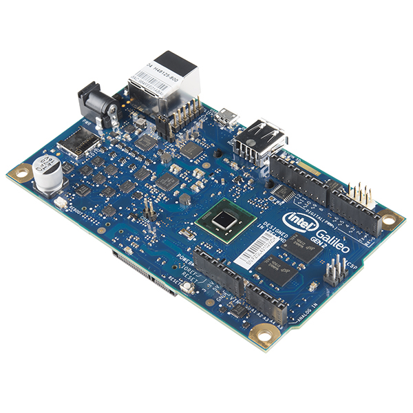
Or Gen 1 if you're a glutton for punishment.
The Intel Galileo Gen 2 has a pin-out form similar to an Arduino Uno. Use the pin numbers as printed on the board, eg. 3, 13, or "A0".
Example:
var five = require("johnny-five");
var Galileo = require("galileo-io");
var board = new five.Board({
  io: new Galileo()
});

board.on("ready", function() {
  var led = new five.Led(13);
  led.blink(500);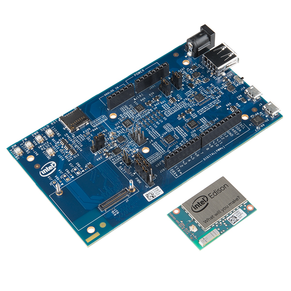
});The Intel Edison + Arduino Breakout has a pin-out form similar to an Arduino Uno. Use the pin numbers as printed on the board, eg. 3, 13, or "A0".
Example:
var five = require("johnny-five");
var Edison = require("galileo-io");
var board = new five.Board({
  io: new Edison()
});

board.on("ready", function() {
  var led = new five.Led(13);
  led.blink(500);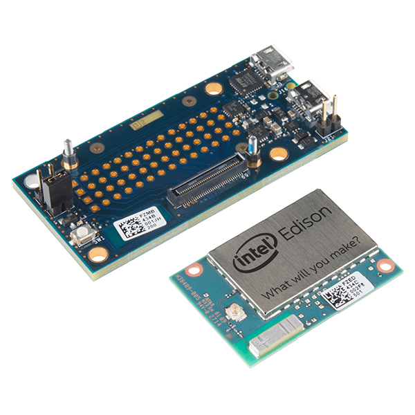
});The Intel Edison + Mini Breakout has a dense pin-out form comprised of four rows, J17, J18, and J19, J20. Each pin is numbered, left-to-right, from 14 to 1 (if looking from the back). Use the row and column name ("J17-1"), or the corresponding GPIO ("GP182"), or pin number 0, to interact with that pin. (Note: "J17-1", "GP182" and 0 refer to the same pin). See the table of valid pins below to determine corresponding Pin names and numbers. *
Connection to bus 1:
| I2C-1-SDA | I2C-1-SCL |
|---|---|
| J17-8 | J18-6 |
Example:
var five = require("johnny-five");
var Edison = require("galileo-io");
var board = new five.Board({
  io: new Edison()
});

board.on("ready", function() {
  var led = new five.Led("J17-1");
  /*
    Same as:

    var led = new five.Led(0);
    var led = new five.Led("GP182");
   */
  led.blink(500);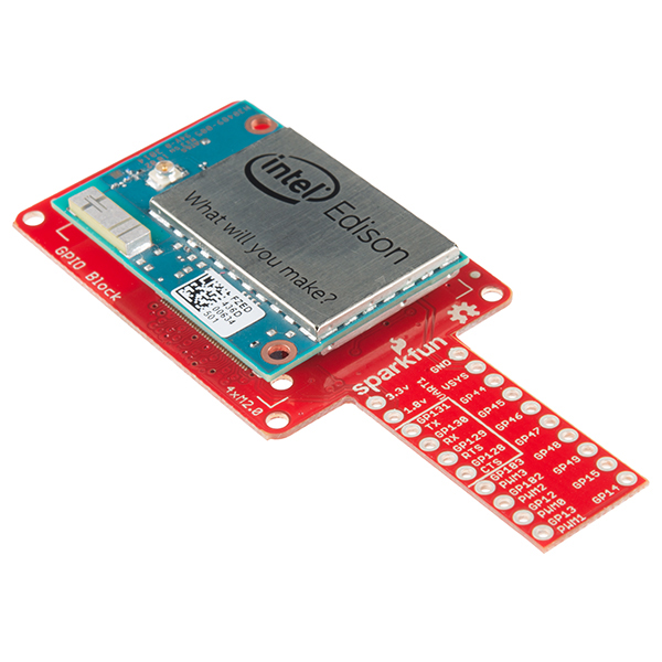
});The SparkFun Edison GPIO Block has two columns of pins. Use the GPIO name printed on the board ("GP44"), or the corresponding row and column name ("J19-4"), or pin number (31), to interact with that pin. (Note: "J19-4", "GP44" and 31 refer to the same pin). See the table of valid pins below to determine corresponding Pin names and numbers. *
Example:
var five = require("johnny-five");
var Edison = require("galileo-io");
var board = new five.Board({
  io: new Edison()
});

board.on("ready", function() {
  var led = new five.Led("GP44");
  /*
    Same as:

    var led = new five.Led(31);
    var led = new five.Led("J19-4");
   */
  led.blink(500);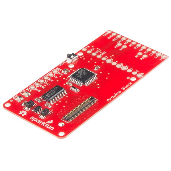
});The SparkFun Edison Arduino Block connects to the Edison via Serial1, or /dev/ttyMFD1. This means that a user must upload StandardFirmata via FTDI programmer. Johnny-Five does not use Galileo-IO to communicate with the hardware on this block, instead it communicates via the serial connection, using its default Firmata.js (this is installed by Johnny-Five automattically. The port name must be specified:
// This code runs on the Edison, communicating with the
// SparkFun Arduino Block via Serial1 (/dev/ttyMFD1)
var five = require("johnny-five");
var board = new five.Board({
  port: "/dev/ttyMFD1"
});

board.on("ready", function() {
  var led = new five.Led(13);
  led.blink(500);
});
Galileo-IO/Edison-IO will automatically connect to bus 1, which is the bus used by this block.
Galileo-IO/Edison-IO will automatically connect to bus 1, which is the bus used by this block.
| Pin Number | Physical Pin | Edison Pin |
|---|---|---|
| 0 | J17-1 | GP182 |
| 4 | J17-5 | GP135 |
| 6 | J17-7 | GP27 |
| 7 | J17-8 | GP20 |
| 8 | J17-9 | GP28 |
| 9 | J17-10 | GP111 |
| 10 | J17-11 | GP109 |
| 11 | J17-12 | GP115 |
| 13 | J17-14 | GP128 |
| 14 | J18-1 | GP13 |
| 15 | J18-2 | GP165 |
| 19 | J18-6 | GP19 |
| 20 | J18-7 | GP12 |
| 21 | J18-8 | GP183 |
| 23 | J18-10 | GP110 |
| 24 | J18-11 | GP114 |
| 25 | J18-12 | GP129 |
| 26 | J18-13 | GP130 |
| 31 | J19-4 | GP44 |
| 32 | J19-5 | GP46 |
| 33 | J19-6 | GP48 |
| 35 | J19-8 | GP131 |
| 36 | J19-9 | GP14 |
| 37 | J19-10 | GP40 |
| 38 | J19-11 | GP43 |
| 39 | J19-12 | GP77 |
| 40 | J19-13 | GP82 |
| 41 | J19-14 | GP83 |
| 45 | J20-4 | GP45 |
| 46 | J20-5 | GP47 |
| 47 | J20-6 | GP49 |
| 48 | J20-7 | GP15 |
| 49 | J20-8 | GP84 |
| 50 | J20-9 | GP42 |
| 51 | J20-10 | GP41 |
| 52 | J20-11 | GP78 |
| 53 | J20-12 | GP79 |
| 54 | J20-13 | GP80 |
| 55 | J20-14 | GP81 |
The "Hello World" of microcontroller programming:
(attach an LED on pin 9)
var Galileo = require("galileo-io");
var board = new Galileo();

board.on("ready", function() {
  var byte = 0;
  this.pinMode(9, this.MODES.OUTPUT);

  setInterval(function() {
    board.digitalWrite(9, (byte ^= 1));
  }, 500);
});Galileo-IO is the default IO layer for Johnny-Five programs that are run on a Galileo or Edison board.
Note: On the Edison, you should require johnny-five first, followed by galileo-io. Otherwise you'll get a segmentation fault.
Example:
var five = require("johnny-five");
var Edison = require("galileo-io");
var board = new five.Board({
  io: new Edison()
});Galileo-IO will do it's best to detect the correct I2C bus to use for a given expansion board, however the process is not infallible. To specify an I2C bus:
// If the i2c bus is 1 (`/dev/i2c-1`)
var board = new Galileo({
  i2c: {
    bus: 1
  }
});
Or...
var board = new Edison({
  i2c: {
    bus: 1
  }
});Expansion boards can also be initialized with a built-in configuration object, that contains the correct I2C bus for that board:
Example:
var five = require("johnny-five");
var Edison = require("galileo-io");
var board = new five.Board({
  io: new Edison(Edison.Boards.Xadow)
});
Or
var five = require("johnny-five");
var Galileo = require("galileo-io");
var board = new five.Board({
  io: new Galileo(Galileo.Boards.Xadow)
});
Additional expansion board configurations will be added as support is implemented
digitalWrite(pin, 1|0)
Sets the pin to 1 or 0, which either connects it to 5V (the maximum voltage of the system) or to GND (ground).
Example:
// This will turn on the pin
board.digitalWrite(9, 1);
analogWrite(pin, value)
Sets the pin to a value between 0 and 255, where 0 is the same as LOW and 255 is the same as HIGH. This is sort of like sending a voltage between 0 and 5V, but since this is a digital system, it uses a mechanism called Pulse Width Modulation, or PWM. You could use analogWrite to dim an LED, as an example.
Example:
// Crank an LED to full brightness
board.analogWrite(9, 255);
servoWrite(pin, value)
Set the pin to a value between 0-180° to move the servo's horn to the corresponding position.
Example:
board.servoWrite(9, 180);digitalRead(pin, handler) Setup a continuous read handler for specific digital pin.
This will read the digital value of a pin, which can be read as either HIGH or LOW. If you were to connect the pin to 5V, it would read HIGH (1); if you connect it to GND, it would read LOW (0). Anywhere in between, it’ll probably read whichever one it’s closer to, but it gets dicey in the middle.
Example:
// Log all the readings for 9
board.digitalRead(9, function(data) {
  console.log(data);
});
analogRead(pin, handler) Setup a continuous read handler for specific analog pin.
This will read the analog value of a pin, which is a value from 0 to 4095, where 0 is LOW (GND) and 4095 is HIGH (5V). All of the analog pins (A0 to A5) can handle this. analogRead is great for reading data from sensors.
Example:
// Log all the readings for A1
board.analogRead("A1", function(data) {
  console.log(data);
});See LICENSE file.