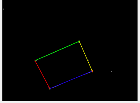
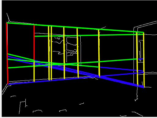
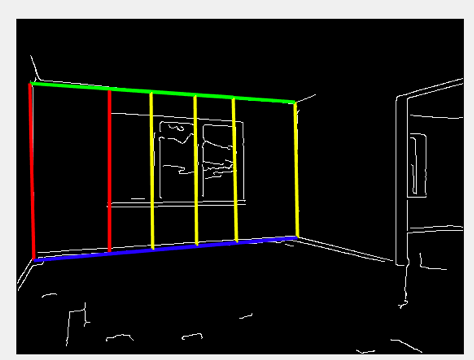
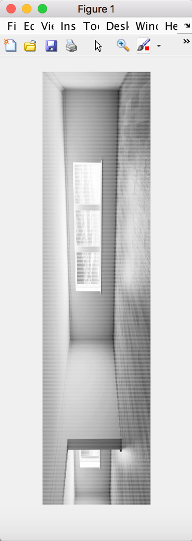
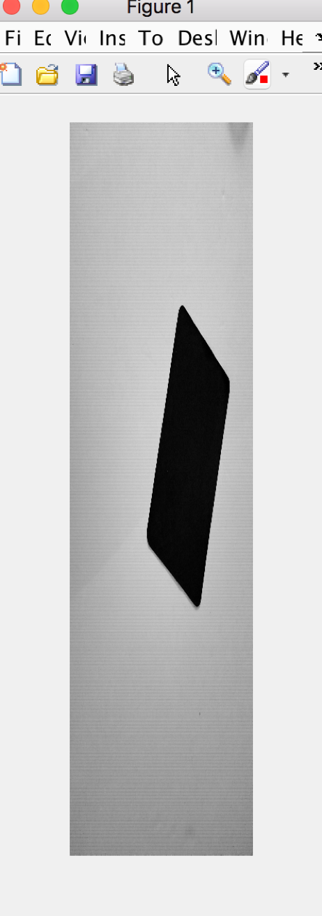
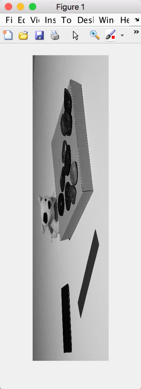
Parallelograms appear frequently in images that contain man-made objects. They often correspond to the projections of rectangular surfaces when viewed at an angle that is not perpendicular to the surfaces. In this project, you are to design and implement a program that can detect parallelograms of all sizes in an image.
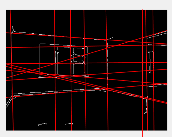
Your program will consist of three steps: (1) detect edges using the Sobel’s operator, (2) detect straight line segments using the Hough Transform, and (3) detect parallelograms from the straight-line segments detected in step (2). In step (1), compute edge magnitude using the formula below and then normalize the magnitude values to lie within the range [0,255]. Next, manually choose a threshold value to produce a binary edge map.
Edge Magnitude = (Gx and Gy are the horizontal and vertical gradients, respectively.)
The test images that will be provided to you are in color so you will need to convert them into grayscale images by using the formula luminance = 0.30R + 0.59G + 0.11B, where R, G, and B, are the red, green, and blue components. Test images in both JPEG band RAW image formats will be provided. In the RAW image format, the red, green, and blue components of the pixels are recorded in an interleaved manner, occupying one byte per color component per pixel (See description below). The RAW image format does not contain any header bytes.
convert them into grayscale images by using the formula luminance = 0.30R + 0.59G + 0.11B
function [gray]=grayimg(img)
%img=imread('TestImage1c.jpg');
R=double(img(:,:,1));
G=double(img(:,:,2));
B=double(img(:,:,3));
gray=0.30*R + 0.59*G + 0.11*B;
%fprintf('%f',max(max(gray3)));
%gray=double(gray3)/double(max(max(gray3)))*255.0;
detect edges using the Sobel’s operator,Sobel operator: $$ \begin{matrix} -1 & 0 & 1 \ -2 & 0 & 2 \ -1 & 0 & 1 \end{matrix} $$
[-1 -2 -1]
Gy= [ 0 0 0]*A
[ 1 2 1]
G= Math.sqrt(Gx^2,Gy^2)
clear;
sourcePic=imread('TestImage3.jpg');
%grayPic=mat2gray(sourcePic);

%have zray l
%newGrayPic=rgb2gray(sourcePic);%convert 3D - 2D
grayPic=grayimg(sourcePic);
%figure;
%imshow(grayPic);
[m,n]=size(grayPic);
newGrayPic=zeros(m,n);
[m,n]=size(newGrayPic);
%newGrayPic2=rgb2gray(sourcePic);
sobelNum=0;
sobelThreshold=40;%1 40; 2 70-80; 3 40
for j=2:m-1
    for k=2:n-1
        sobelNum=sqrt((grayPic(j-1,k+1)+2*grayPic(j,k+1) ...
            +grayPic(j+1,k+1)-grayPic(j-1,k-1)-2*grayPic(j,k-1)-grayPic(j+1,k-1))^2+ ...
            (grayPic(j-1,k-1)+2*grayPic(j-1,k)+grayPic(j-1,k+1)-grayPic(j+1,k-1) ...
            -2*grayPic(j+1,k)-grayPic(j+1,k+1))^2);
        if(sobelNum > sobelThreshold)
            newGrayPic(j,k)=255;
        else
            newGrayPic(j,k)=0;
        end
    end
end
figure;
imshow(newGrayPic)
title('Sobel operator')
lose data through converting, see in src to see details
function[m,theta,sector,canny1,canny2,bin]=canny1step(src,lowTh,highTh)
[Ay,Ax,dim]=size(src);
//lose data through converting, see in src to see details
if dim >
	src=rgb2gray(src);
end
src=double(src);
m=zeros(Ay,Ax);
theta=zeros(Ay,Ax);
sector=zeros(Ay,Ax);
canny1=zeros(Ay,Ax);%??????
canny2=zeros(Ay,Ax);%????????
bin=zeros(Ay,Ax);
for y=2:(Ay-1)
    for x=2:(Ax-1)
	gx=src(y-1,x+1)+2*src(y,x+1)+src(y+1,x+1)-...
	src(y-1,x-1)-2*src(y,x-1)-src(y+1,x-1);
	gy=src(y+1,x-1)+2*src(y+1,x)+src(y+1,x+1)...
	-src(y-1,x-1)-2*src(y-1,x)-src(y-1,x+1);
	m(y,x)=(gx^2+gy^2)^0.5;
%--------------------------------
	theta(y,x)=atand(gx/gy);
	tem=theta(y,x);
%--------------------------------
	if(tem<67.5)&&(tem>22.5)
	    sector(y,x)=0;
	elseif(tem<22.5)&&(tem>-22.5)
	    sector(y,x)=3;
	elseif(tem<-22.5)&&(tem>-67.5)
	    sector(y,x)=2;
	else
	    sector(y,x)=1;
	end
%--------------------------------
    end
end
%-------------------------
%??????
%------>x
%210
%3X3
%y012
for y=2:(Ay-1)
    for x=2:(Ax-1)
	ifsector(y,x)==0%??-??
	    if(m(y,x)>m(y-1,x+1))&&(m(y,x)>m(y+1,x-1))
		canny1(y,x)=m(y,x);
	    else
		canny1(y,x)=0;
    	    end
	elseifsector(y,x)==1%????
	    if(m(y,x)>m(y-1,x))&&(m(y,x)>m(y+1,x))
		canny1(y,x)=m(y,x);
	    else
		canny1(y,x)=0;
	    end
	elseifsector(y,x)==2%??-??
	    if(m(y,x)>m(y-1,x-1))&&(m(y,x)>m(y+1,x+1))
		canny1(y,x)=m(y,x);
	    else
		canny1(y,x)=0;
	    end
	elseifsector(y,x)==3%???
	    if(m(y,x)>m(y,x+1))&&(m(y,x)>m(y,x-1))
		canny1(y,x)=m(y,x);
	    else
		canny1(y,x)=0;
	    end
	end
    end%end for x
end%end for y


for y=2:(Ay-1)
    for x=2:(Ax-1)
	if canny1(y,x)<lowTh%?????
	    canny2(y,x)=0;
	    bin(y,x)=0;
	    continue;
	elseif canny1(y,x)>highTh%?????
	    canny2(y,x)=canny1(y,x);
	    bin(y,x)=1;
	    continue;
	else%???????8???????????????????
	    tem=[canny1(y-1,x-1),canny1(y-1,x),canny1(y-1,x+1);
	    canny1(y,x-1),canny1(y,x),canny1(y,x+1);
	    canny1(y+1,x-1),canny1(y+1,x),canny1(y+1,x+1)];
	    temMax=max(tem);
	    if temMax(1)>highTh
	    	canny2(y,x)=temMax(1);
	    	bin(y,x)=1;
	    	continue;
	    else
	    	canny2(y,x)=0;
	    	bin(y,x)=0;
	    	continue;
	    end
	end
    end %end for x
end %end for y
end%end of function
function[h,theta,rho]=houghTs(f,dtheta,drho)
if nargin<3
    drho=1;
end
if nargin<2
    dtheta=1;
end
f=double(f);
[M,N]=size(f);
theta=linspace(-90,0,ceil(90/dtheta)+1);
theta=[theta-fliplr(theta(2:end-1))];
ntheta=length(theta);
D=sqrt((M-1)^2+(N-1)^2);
q=ceil(D/drho);
nrho=2*q-1;
rho=linspace(-q*drho,q*drho,nrho);
[x,y,val]=find(f);
x=x-1;y=y-1;
%Initializeoutput.
h=zeros(nrho,length(theta));
%Toavoidexcessivememoryusage,process1000nonzeropixel
%valuesatatime.
for k=1:ceil(length(val)/1000)
    first=(k-1)*1000+1;
    last=min(first+999,length(x));
    x_matrix=repmat(x(first:last),1,ntheta);
    y_matrix=repmat(y(first:last),1,ntheta);
    val_matrix=repmat(val(first:last),1,ntheta);
    theta_matrix=repmat(theta,size(x_matrix,1),1)*pi/180;
    rho_matrix=x_matrix.*cos(theta_matrix)+...
    y_matrix.*sin(theta_matrix);
    slope=(nrho-1)/(rho(end)-rho(1));
    rho_bin_index=round(slope*(rho_matrix-rho(1))+1);
    theta_bin_index=repmat(1:ntheta,size(x_matrix,1),1);
    h=h+full(sparse(rho_bin_index(:),theta_bin_index(:),...
    val_matrix(:),nrho,ntheta));
end

function[r,c,hnew]=hpeak(h,nhood)
if nargin<2
    nhood=size(h)/50;
    %Makesuretheneighborhoodsizeisodd.
    nhood=max(2*ceil(nhood/2)+1,1);
end
hmax=max(h(:));
hnew=h;r=[];c=[];
[hm,hn]=size(h);
localmaxa=80;%2nd80;3rd5
localmaxb=10;%2nd10;3rd5
for ha=1+localmaxa:localmaxa*2:hm-localmaxa
    for hb=1+localmaxb:localmaxb*2:hn-localmaxb
	hnewp=hnew(ha-localmaxa:ha+localmaxa,hb-localmaxb:hb+localmaxb);
	if(max(hnewp(:))~=0&&max(hnewp(:))>=hmax*0.2)%2nd0.23rd0.15
 	    [p,q]=find(hnewp==max(hnewp(:)));
	    p=p+ha-localmaxa-1;
	    q=q+hb-localmaxb-1;
	    p=p(1);q=q(1);
	    r(end+1)=p;c(end+1)=q;
	end
    end
end


