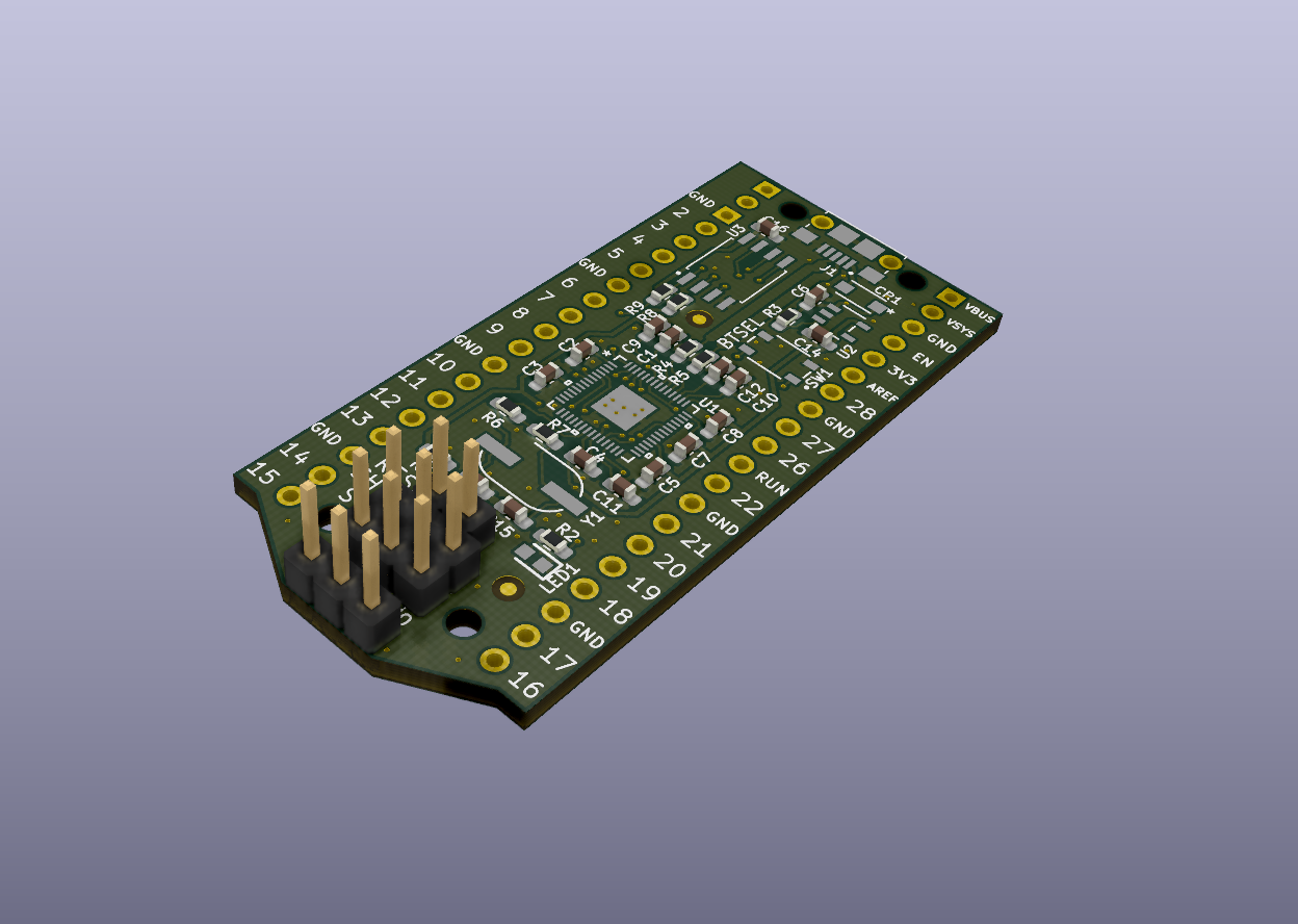
Stackable debugger board for the Raspberry Pi Pico. Solder long headers to this debugger board in order to connect the Pico to it. You will also need to connect jumper wires from the bottom CLK, GND, DIO pins to the target pico.
All design files were created using KiCad v5.1.
Feel free to modify this design for your own applciation. This PCB is intended to be a project for testing the layout of the Raspberry Pi RP2040.
Recommended reading:
Schematic and PCB layout files are licensed under the CC BY 4.0 license.
THE DESIGN IS PROVIDED "AS IS" AND THE AUTHOR DISCLAIMS ALL WARRANTIES WITH REGARD TO THIS DESIGN INCLUDING ALL IMPLIED WARRANTIES OF MERCHANTABILITY AND FITNESS. IN NO EVENT SHALL THE AUTHOR BE LIABLE FOR ANY SPECIAL, DIRECT, INDIRECT, OR CONSEQUENTIAL DAMAGES OR ANY DAMAGES WHATSOEVER RESULTING FROM LOSS OF USE, DATA OR PROFITS, WHETHER IN AN ACTION OF CONTRACT, NEGLIGENCE OR OTHER TORTIOUS ACTION, ARISING OUT OF OR IN CONNECTION WITH THE USE OR PERFORMANCE OF THIS DESIGN.
