License: CC BY-SA 4.0
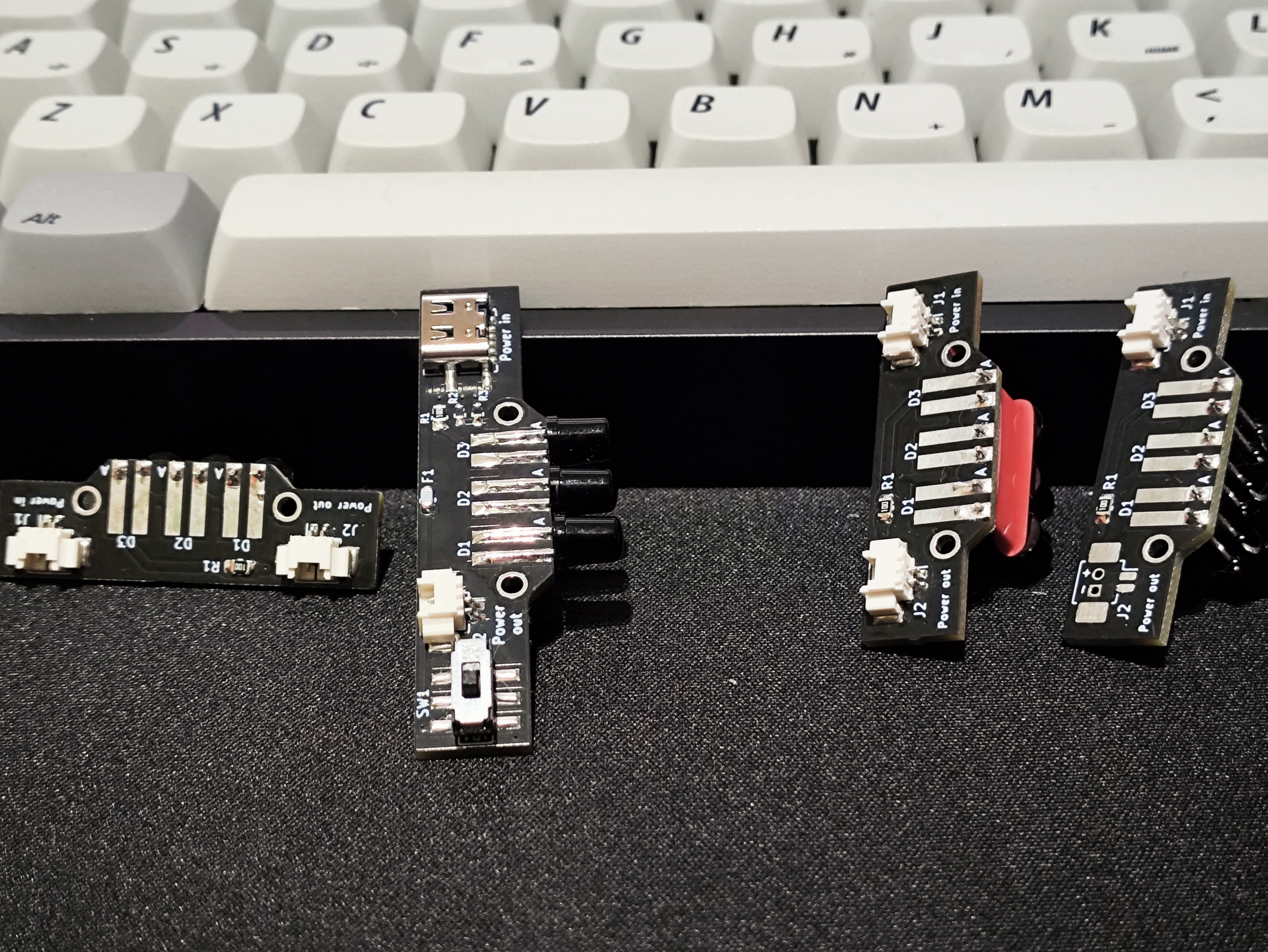
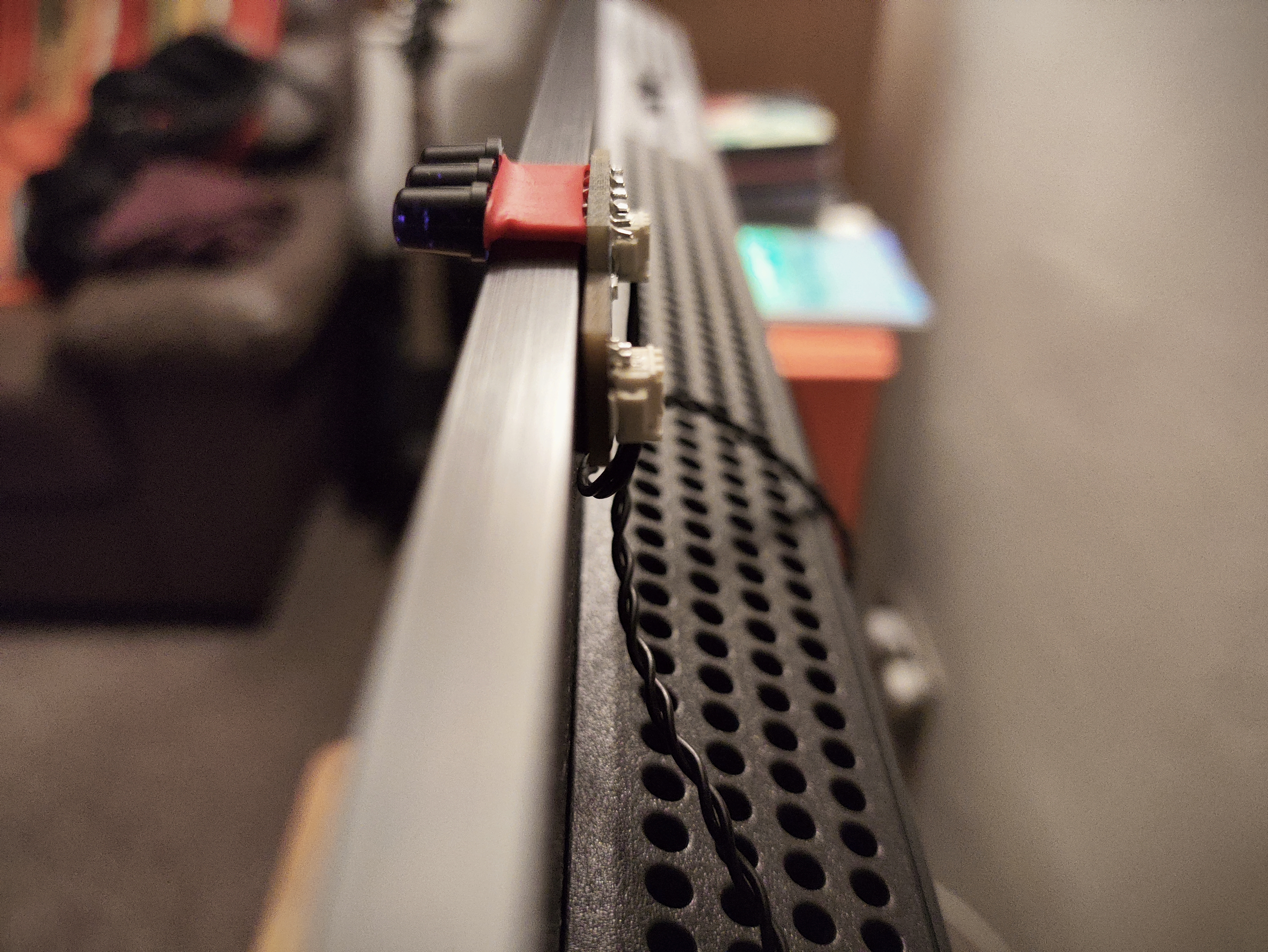
An IR LED emitter setup, for use with the Wii or IR-based light guns with a focus on remaining as slim as possible, with no components on the back of the board to allow mounting directly to a display
Grab the gerbers from the latest release and upload to your favourite PCB fab (OSHPark, Aisler, JLCPCB). Default settings should be fine - I wouldn't recommend getting the boards any thinner than 1.6mm as may restrict your mounting options.
HASL is a-ok to use and generally the cheapest option, so would recommend this as the surface finish.
- Soldering iron
- Solder (recommend relatively thin solder - this will make it easier to avoid bridging pins by adding too much)
- Flux (will help keep your joints shiny and happy)
- Tweezers
- Wire crimping tool (if not buying preassembled cables)
Assembly is possible with just an iron, but be super sure to get the USB-C and Molex Picoblade connectors correctly aligned before you tin more than one pad - they're tricky to fix mistakes on without hot air or a hot plate.
There are a few options that will work for any given setup but I'll outline the ones most likely to be appealing
Wii / 2IR light guns only:
- 1x power-emitter + 1x emitter
- 1x power-4ir + 2x emitter (you can skip populating 2 Picoblade connectors)
4IR light guns only (Gun4IR / OpenFIRE):
- 1x power-emitter + 3x emitter
- 1x power-4ir + 4x emitter
Wii / 2IR light guns and 4IR light guns in square layout (OpenFIRE):
- 1x power-42-square + 4x emitter
Wii / 2IR light guns and 4IR light guns in diamond layout (Gun4IR):
- 1x power-42-diamond + 6x emitter
I swear I'll flesh this out later but here's how I'd go about soldering up the simplest setup of power-emitter + emitter. Any other setup is basically more of the same.
- First, solder the USB connector to J1 onto the power-emitter board. If using an iron, I'd tin one of the outer pads and move the port into place while keeping this molten (without lingering too long, of course!) - Once you're happy with the alignment, add a little solder to the other pads. Be sure plenty to get good strong joints on the shielding - these will be providing the bulk of the mechanical strength keeping the port in place. If you bridge any pads, try adding some flux and introducing a nice clean iron tip.
- Add the Molex connectors to both boards - J2 on the power-emitter, J1 on the emitter. Similar to the USB port, I've had most success lining up one of the pads, then once aligned properly move onto the mounting points and then the remaining pad.
- You don't need to populate J2 on an emitter board unless you're connecting additional emitters through it
- In this revision, emitter boards have swapped polarity between the 'Power in' and 'Power out' Picoblade connectors; this is to ensure you can use the pre-made cable assemblies that do not cross over the wires. If you choose to crimp your own cables, be sure to account for this.
- Add the resistors, and the F1 on the power-emitter board. Tin a single pad and introduce the component, then add solder to the other side. If you're using a tip with significant thermal mass, don't hang about for long; you may melt the solder on the other side through the component. An 0603 resistor will happily float away with the surface tension on your iron and make a new home on it.
- I'd strongly recommend populating R2 and R3 (5.1K) on the power-emitter board as they'll allow USB C to C cables to be used but if this isn't important to you, feel free to omit them.
- Add the LEDs. The LEDs can be soldered flat against the board so they stick out of the front (recommended when mounting under a display), or through-hole (can help if mounting emitters around the edge of a really thin display). The pad labelled with an A is for the anode (positive) leg. If you're using LEDs with a shallow viewing angle, you may want to angle the outer LEDs slightly to increase effective viewing angles but the SFH 4547 are fine firing straight outwards.
- Lastly, add the switch to the power-emitter board. Handily, orientation does not matter!
- Alternatively, you can bridge the jumper J1 with a blob of solder to force the board to be always on when plugged in. If you anticipate a total power draw over over 600mA, you might want to do this as you'd be exceeding the switch's rating otherwise (300mA per pole - they're both tied together on this PCB).
Once you're done, plug in your cable between the Power out of the power-emitter board and the Power in on the emitter anddddd fingers crossed, you have light! The IR LEDs in the BOM aren't visible to the naked eye, so you may want to use a phone to test (I've heard iPhones like to filter IR out, though)
If you want a nice enclosure to keep things looking tidy, RayneX has made some brilliant shells on Printables.
There are enclosures for the emitter boards and the power-42-square board (which should also fit the latest revision of the power-4ir board, but this is untested at present).
- Take some nice pictures of common setups
- Video showing assembly? Ugh

