Sonoff IFAN04 with ESPHome
This ESPHome configuration file reproduces the functionality of the original IFAN04 firmware. Additinally it enables the use of the I2C bus.
It took me a little bit longer than expected, but now the new mostly reworked version is finished and tested. :-)
I completely changed the timing and control of the fan relays. The state changes and, if enabled, the buzzer are processed by parameterized scripts. So it is more flexible and easier to customize. I have also implemented many additional switches and sensor to send information to Home Assistant and configure the iFan04 via Home Assistant. I also added a SHT3x sensor to demonstrate the I2C abilities.
- Light enabled - Activates the ability to switch the light relay via remote control
- Fan startup-boost enabled - Enables the startup-boost, if the fan is turned on (see Fan control and timing for more details)
- Restart - Restart the iFan04
- Remote button light - Binary sensor which is activated for 500ms if the remote control button "Light" (top left) was pressed
- Remote button link - Binary sensor which is activated for 500ms if the remote control button "Link" (bottom left or right) was pressed
- Text sensor with WiFi informations (ip address, ssid, mac address, dns address)
- Temperatur and humidity via SHT3x I2C sensor for demonstration
Configurable 5 speed mode (off, low, mid-low, mid-high, high). If you replace the condensators on the pcb it might be usefull the have the ability to enabled them individually and combined. As a result you get 5 different speed modes.
- all off
- no cap (relay 3)
- cap 1 (relay 1)
- cap 2 (relay 2)
- cap 1 & 2 (relay 1 & 2)
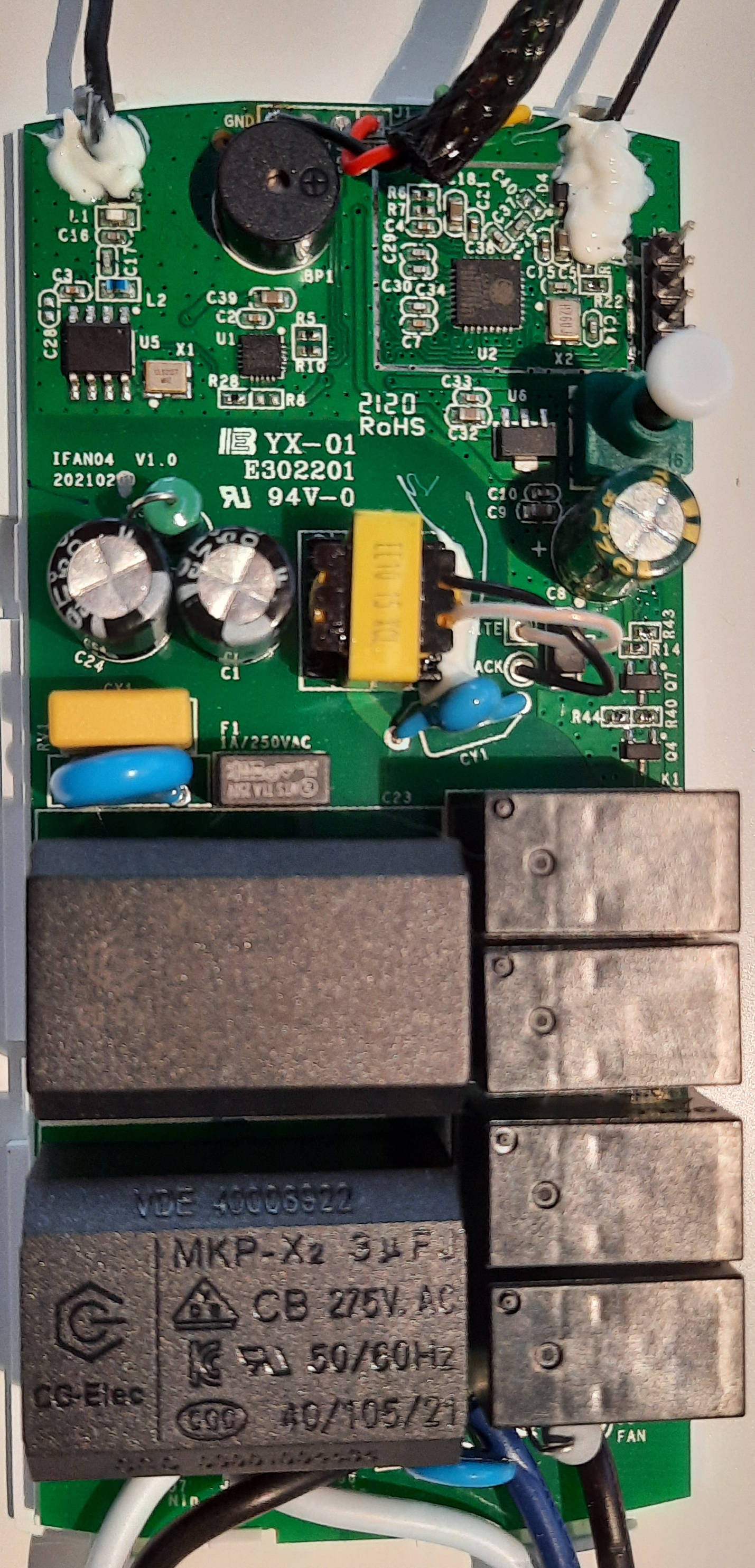
IFAN04 has a ESP8266 with 1 MB flash.
The RF remote control receiver communicates with the ESP8266 via the UART0 serial interface. Baudrate is 9600.
The fan and light is controlled with four relays.
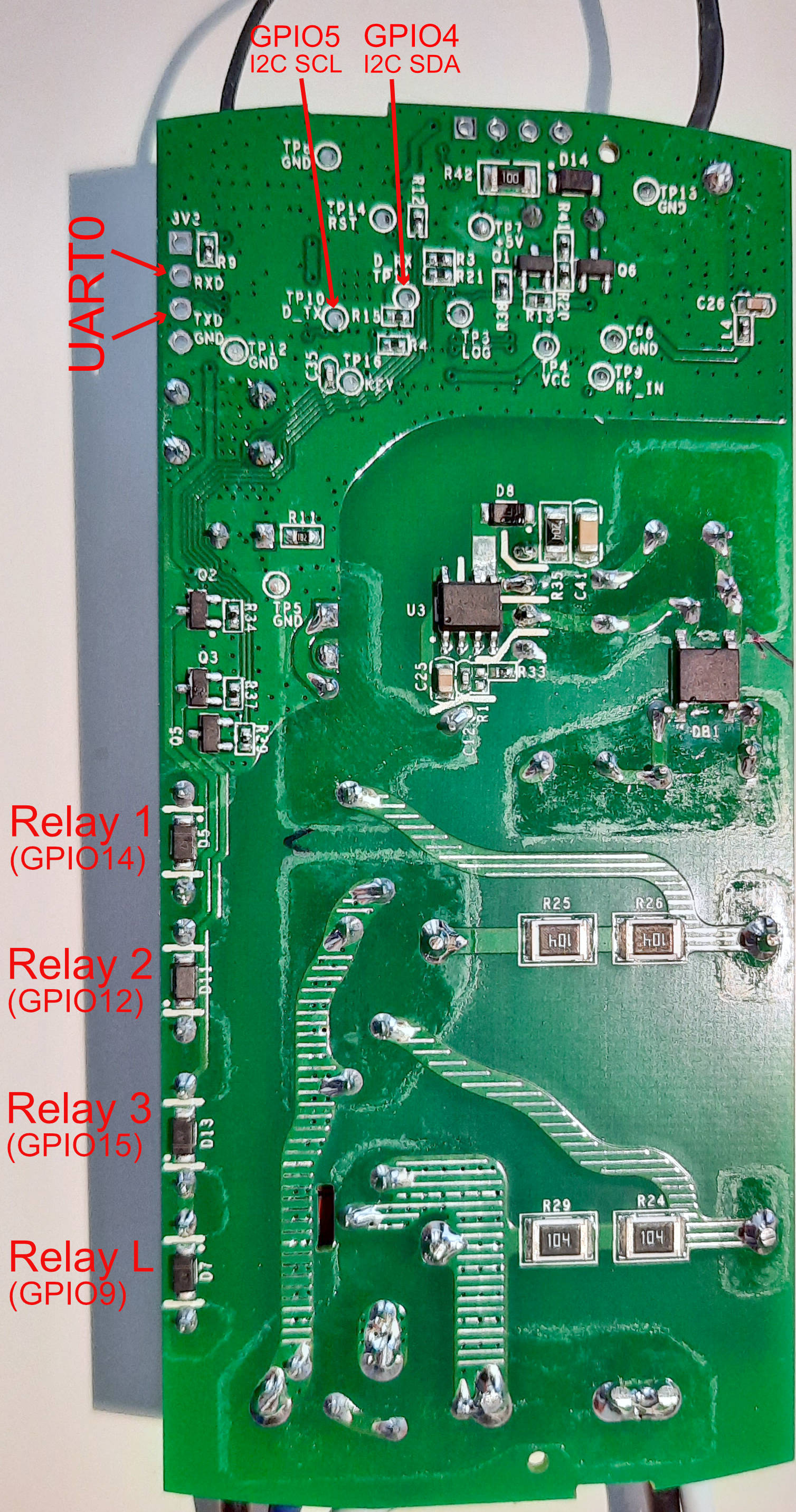
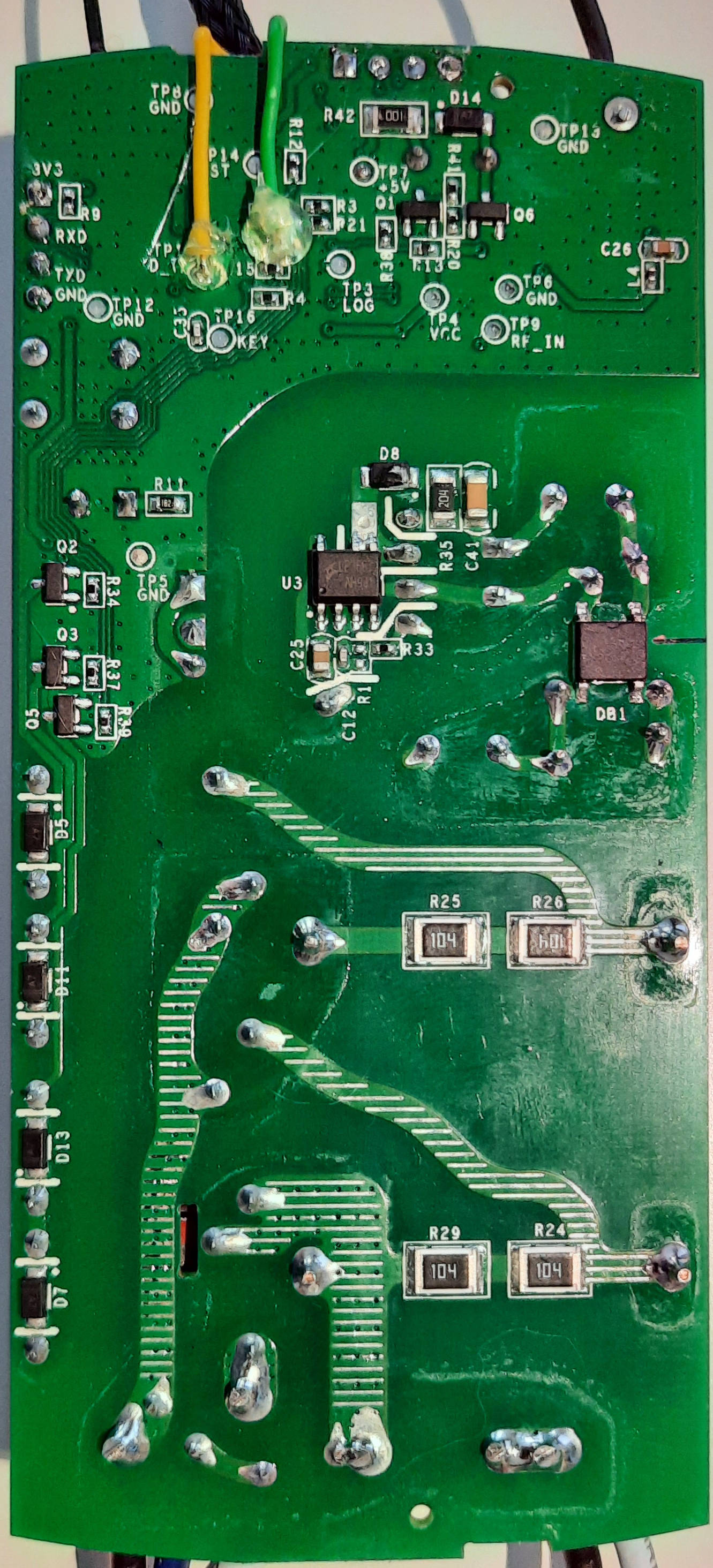
To use the I2C interface of the ESP8266 the SDA and SCL pins can be accessed through the test pins (TP10, TP11) on the backside of the PCB.
| ESP pin | assignment | comments |
|---|---|---|
| GPIO0 | Button | |
| GPIO1 | UART0 TX | |
| GPIO3 | UART0 RX | RF remote control receiver |
| GPIO4 | I2C SDA | TP11 D_RX on the PCB backside |
| GPIO5 | I2C SCL | TP10 D_TX on the PCB backside |
| GPIO9 | Light relay | D7 on the PCB backside |
| GPIO10 | Buzzer | |
| GPIO12 | Fan relay 2 | D11 on the PCB backside, 3 uF on IFAN04-H |
| GPIO13 | LED | |
| GPIO14 | Fan relay 1 | D5 on the PCB backside, 2.5 uF on IFAN04-H |
| GPIO15 | Fan relay 3 | D13 on the PCB backside, no cap |
The three different speeds (low, mid, high) are controlled via the three fan relays as follows.
| Fan speed | used relays |
|---|---|
| low | 1 |
| mid | 1 + 2 |
| high | 3 |
In the new version I have changed the timing sequence completely. Now, if the fan is turned on and startup-boost is enabled, the fan is started with high speed for the time configured via the substitution variable "fan_startup_boost_time". After this time the speed is changed to the selected one (low or mid speed). If startup-boost is disabled, the fan speed is immmediatly set to the selected one (low, mid, high).
The original firmware had the following special timing sequence on activating the different speeds.
| Fan speed | timing sequence |
|---|---|
| low | relay 1 + 2 are turned on, after 5 seconds relay 2 is turned off |
| mid | relay 1 + 2 are turned on |
| high | relay 1 is turned on, after 5 seconds relay 3 is turned on and relay 1 is turned off |
RF remote control receiver sends the remote control commands via the serial interface UART0 to the ESP8266.
These commands consits of 8 bytes. The first two bytes are always 0xAA55 and the last byte is a checksum of the bytes 3 to 7, the command code.
To receive and use these commands in ESPHome the serial data is processed by a custom text sensor component.
This text sensor component is implemented in the ifan_remote.h file and receives and translates the commands of the remote control into the following text strings.
| RC button | text string | label |
|---|---|---|
| 1 (left-top) | 0104000104 | Light on/off |
| 2 | 0106000101 | Mute |
| 3 | 0104000103 | High speed |
| 4 | 0104000102 | Medium speed |
| 5 | 0104000100 | Fan off |
| 6 | 0104000101 | Low speed |
| 7 | 0101000102 | RF clearing |
| 8 (right-bottom) | 0101000102 | Wi-Fi pairing |
The two bottom buttons are sending the same command code to the ESP8266.
The custom text sensor is implemented in the configuration file as follows:
esphome:
  includes:
    - ifan_remote.h

logger:
  baud_rate: 0

uart:
  rx_pin: GPIO03
  baud_rate: 9600
  id: uart_bus

text_sensor:
  - platform: custom
    lambda: |-
      auto ifan_remote_sensor = new IFanRemote(id(uart_bus));
      App.register_component(ifan_remote_sensor);
      return {ifan_remote_sensor};
    text_sensors:
      name: 'RC command'
      on_value:
        then:
          - if: # Light on/off
              condition:
                lambda: return x == "0104000104";
              then:
                ...
As you can see to use the RF remote control the uart debugging must be disabled by setting baud_rate: 0 in the logger-configuration.


