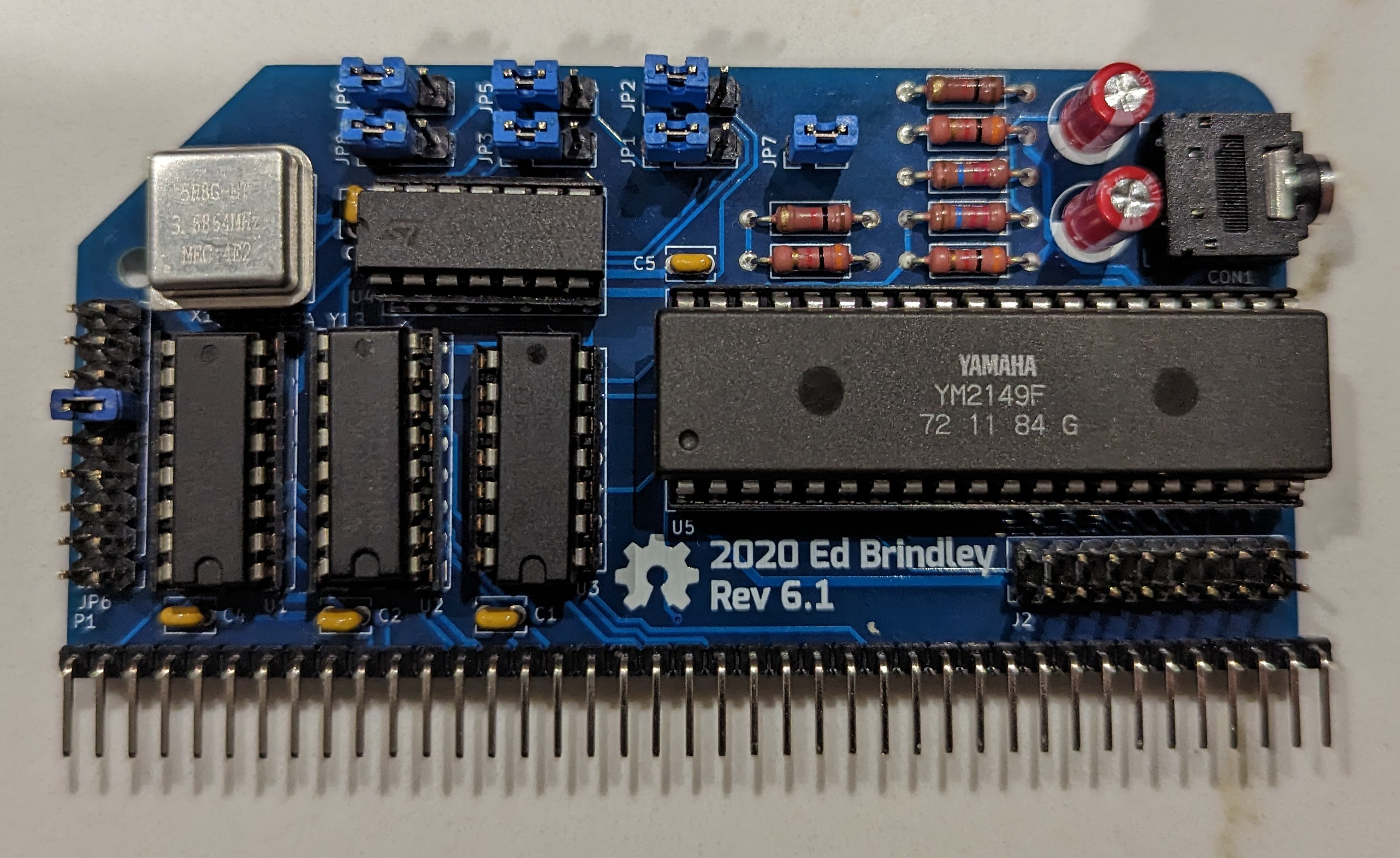
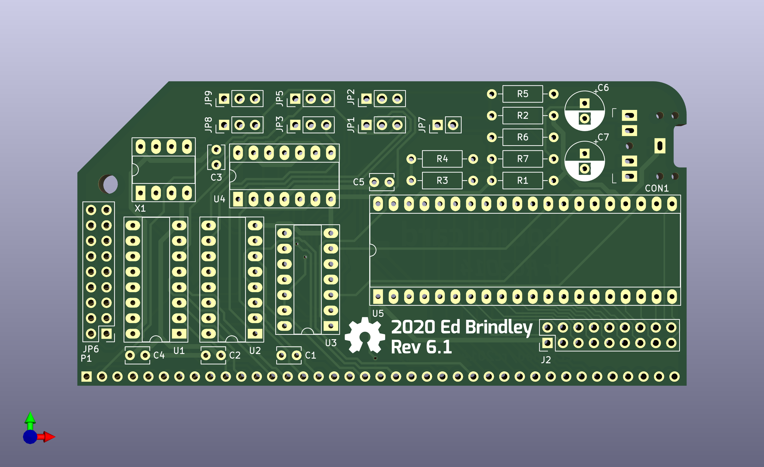
The head of this repository contains the latest version - currently Rev 6.1. Please check the version of your board, and select the appropriate tag from the right to get the documentation for your board. e.g go here for the Rev 5 (most common) docs
Video demonstration: https://www.youtube.com/watch?v=-iLwi9FagFE
This is a YM2149F/AY-3-8910 sound card for the RC2014 Z80 8-bit computer. It adds the ability to play music on your RC2014!
- Playing music for MSX or ColecoVision Super Game Module compatible software (you may also want a TMS9918A board)
- Playing music ripped from spectrum games
- Playing Spectrum Protracker 2/3 and tunes in MYM format
- Adding music to your own games
- Making music from BASIC or ASM!
- Stereo Line out, with golden ratio mixer.
- Header for the 2 8-bit I/O ports. These could be used for reading from joysticks, additional serial ports, LED indicators etc.
- Both YM2149F and AY-3-8910 ICs may be used
- Supported in RomWBW
- Possible to jumper to the same IO port as the ZX Spectrum AY
- Known to work on the standard RC2014 setup, as well as on Steve Cousin's SC126 and SC130
- Divides the RC2014 clock by 2 or 4 using flip flops to bring it under the 2Mhz max clock speed of the AY.
- Supports enabling the YM2149F's internal clock divider. This means that bus speeds up to 16Mhz could be supported without overclocking the chip. (AY does not have this feature)
- George Beckett has done some great work getting the board working on the Minstrel 4th Jupiter Ace compatible computer. See his repository here for information.
The Yamaha YM2149F and General Instrument AY-3-8910 are popular sound chips that were used in a wide variety of computers and arcade machines in the 1980s and 1990s. The most notable of those being the ZX Spectrum 128, Atari ST and MSX computers.
- If you have bought one of Spencer's kits, obtain a YM2149 chip from your local friendly eBay seller :)
- Verify the components supplied in the kit match up with bill of materials
- Solder the components to the board, matching the components in the BOM to the component references printed on the PCB, starting with the lowest height ones first e.g. bypass capacitors and resistors, then moving on to IC sockets, pin headers and do the electrolytic capacitors and output jack last.
- Insert the ICs in their sockets. The component reference marking on the PCB (e.g. U1) is nearest to pin 1 for all ICs
- If you have a Z80 based system, configure the jumpers on the board so it looks like the picture in the README. This will ensure it is at the right IO address.
- Insert board into backplane/SBC
- Boot into RomWBW ensure you have the "tune.com" application (it's not included in the ROM drive but should be on the disk images)
- Find some music to play. There are some example files in https://github.com/wwarthen/RomWBW/tree/dev/Source/Apps/Tune/Tunes that you could transfer to the system.
- Use tune.com to play the music file. If you download the RomWBW*-Package.zip corresponding to whatever version of RomWBW you are using the from the releases page here https://github.com/wwarthen/RomWBW/releases, the tune.com executable will be in the
Binary/Appsdirectory.
| Qty | Schematic Reference | Description |
|---|---|---|
| 2 | U1 U2 | 16 pin DIP socket 2.54 mm pin pitch, 7.62 mm wide |
| 1 | U5 | 40 pin DIP socket, 2.54mm pin pitch, 15.24mm wide |
| 1 | U5 | Yamaha YM2149F or General Instrument AY-3-8910 |
| 1 | U4 | 74HCT74 |
| 2 | U3 U4 | 14 pin DIP socket 2.54 mm pin pitch, 7.62 mm wide |
| 1 | U3 | 74HCT00 |
| 2 | U1 U2 | 74HCT138 |
| 2 | R6 R7 | 1k6 ohm 1/4 watt metal film resistor |
| 2 | R4 R5 | 1k ohm 1/4 watt metal film resistor |
| 3 | R1 R2 R3 | 3k ohm 1/4 watt metal film resistor |
| 1 | P1 | 40 pin right angled 2.54mm header |
| 1 | CON1 | 3 or 5 pin 3.5mm PCB mount jack socket (e.g. SJ1-3525N - mouser part 710-860020472001) |
| 2 | C6 C7 | 4.7uF electrolytic capacitor |
| 5 | C1 C2 C3 C4 C5 | 0.1uF ceramic capacitor 2.54 mm pin pitch |
| 7 | JP1-5 JP8-JP9 | 3 x 1 straight pin header 2.54 mm pin pitch |
| 1 | JP7 | 2 x 1 straight pin header 2.54 mm pin pitch |
| 1 | JP6 | 9 x 2 straight pin header 2.54 mm pin pitch |
| 1 | J2 | 9 x 2 straight pin header 2.54 mm pin pitch |
| 1 | X1 | Half size Oscillator socket (or DIP-8 socket with middle pins removed) |
| 5 | Various | Jumpers |
The majority of the components are widely available, however both the AY-3-8910 and YM2194F are unfortunately not in production any more, but reclaimed chips are available fairly plentifully on eBay from suppliers in China. I would suggest using a standard 40 pin DIL socket for the AY as they are more accommodating to bent/soldered pins than a turned pin ones.
The board contains a set of jumpers to select the address at which the sound chip will respond to commands. The jumpers settings are described in detail below.
"Normal" or MSX addressing mode is recommended.
MSX mode uses standard 8-bit port addressing. This board allows the base address to be any value from 00-F0 (MSX uses A0 and ColecoVision SGM uses 50 for the PSG's base address). Different ports in the lower nybble are used for reading and writing the address and data registers. Writing to port X0h selects the PSG register. Writing to port X1h writes the selected PSG register value and reading port X2h reads the selected PSG register value.
i.e. for MSX: Configure base address: A0h Register write address: A0h Data write address: A1h Data read address: A2h
and ColecoVision Configure base address: 50h Register write address: 50h Data write address: 51h Data read address: 52h
ZX Spectrum mode uses an uncommon 16-bit I/O addressing scheme for the PSG. This is possible since the Z80 puts the value of the B register on the upper 8 bits of the address bus when performing an IN r, (C) or OUT (C), r instruction. Setting A15 to 1 and A1 to 0 enables the PSG and A14 distinguishes between PSG address and data registers. To select a PSG register, set BC to FFFDh and use OUT (C), r to select the address in r. To write a value to the selected PSG register set BC to BFFDh and use OUT (C), r to write the value in r. To read the selected PSG register value, set BC to FFFDh and use IN r, (C). Note that r must be A, D, E, H, or L since B and C are required for addressing. Also note that OUT (n), A and IN A, (n) instructions won't work since they put the value of A on the upper 8 bits of the address bus.
REV6 no longer supports the D0/D8 addresses used by default in REV5 and earlier. REV6 introduced MSX-compatible addressing and supporting addresses used by REV5 and earlier would have required additional chips. This seems like a fair tradeoff since existing software that uses the original default addresses for this board is minimal compared to software that uses the MSX or Spectrum addressing schemes.
Note: Pin 1 on each jumper is identified by having square pad.
Select between MSX and ZX Spectrum decoding. All 3 jumpers should all be set to either MSX or ZX Spectrum mode. For Spectrum mode, JP6 must also be set in position 17-18. Mixing modes on different jumpers will result in nonsensical address decoding.
| pins | description |
|---|---|
| 1-2 (Left Position) | Normal/MSX/ColecoVision |
| 2-3 (Right Position) | ZX Spectrum |
Selects the upper or lower half of the address range selected by JP6.
| pins | description |
|---|---|
| 1-2 (Left position) | Upper (odd) half |
| 2-3 (Right position) | Lower (even) half |
Selects the base address for MSX addressing mode. For Spectrum addressing, the rightmost position (17-18) must be used. MSX addressing can use any base address from 00-F0, where JP6 selects the 3 most significant bits. JP5 is used to set A4, thus selecting the lower or upper half of the range chosen by JP5.
| pins | with JP5 on 1&2 |
|---|---|
| 1-2 (Bottom most position) | 0x00 |
| 3-4 | 0x20 |
| 5-6 | 0x40 |
| 7-8 | 0x60 |
| 9-10 | 0x80 |
| 11-12 | 0xA0 (MSX Compatible) |
| 13-14 | 0xC0 |
| 15-16 | 0xE0 |
| 17-18 (Top most position) | Spectrum Mode |
| pins | with JP5 on 2&3 |
|---|---|
| 1-2 (Bottom most position) | 0x10 |
| 3-4 | 0x30 |
| 5-6 | 0x50 (ColecoVision SGM compatible) |
| 7-8 | 0x70 |
| 9-10 | 0x90 |
| 11-12 | 0xB0 |
| 13-14 | 0xD0 |
| 15-16 | 0xF0 |
| 17-18 (Top most position) | Spectrum Mode |
YM2149 only, internally halve clock if jumpered
Use bus clock or onboard oscillator
| pins | description |
|---|---|
| 1-2 | Oscillator |
| 2-3 | Bus clock |
Clock divisor. Divides the bus or oscillator
| pins | description |
|---|---|
| 1-2 | Divide by 2 |
| 2-3 | Divide by 4 - Default |
CON1 - 3.5mm audio out
J2 - 2 8 bit I/O ports
See the BASIC programs in player/test. descend.bas plays some descending tones, io_in.bas demonstrates reading from the IO port, and io_out.bas demonstrates writing to an IO port.
Wayne has incorporated a player called "Tune" into RomWBW that will play PT2, PT3 and MYM files. See here for the source: https://github.com/wwarthen/RomWBW/tree/master/Source/Apps/Tune. It should be present within RomWBW disk images.
Alternatively start the Microsoft BASIC interpreter mbasic, and refer to the above BASIC examples.
#A0 (write) Register write port #A1 (write) Value write port #A2 (read) Value read port
ZXArt is my favourite site: https://zxart.ee/eng/music/mainpage/
http://zxtunes.com/ is another massive collection.
http://ftp.kameli.net/pub/mym/ has a collection of MYM files
This tool compresses YMs to MYMs, which makes a lot of music available: http://osdk.org/index.php?page=documentation&subpage=ym2mym although your mileage may vary, I found some YMs weren't convertible.
This is a large archive of YM tunes to try with the above tool: ftp://ftp.modland.com/pub/modules/YM/
The CPC Power site has a lot of Amstrad YMs: https://www.cpc-power.com/index.php?page=database
There are some PT2s, PT3s and YMs on Sergei Bulba's site: http://bulba.untergrund.net/music_e.htm (although a lot of tunes in other formats)
- Some ideas and the golden ratio output mixing were taken from the Melodik 2 design here: http://hw.speccy.cz/melodik2.html
- MSX decoding, many thanks to J.B. Langston
Copyright Ed Brindley 2017-2022.
This source describes Open Hardware and is licensed under the CERN-OHL-P v2 You may redistribute and modify this documentation and make products using it under the terms of the CERN-OHL-P v2 (https:/cern.ch/cern-ohl). This documentation is distributed WITHOUT ANY EXPRESS OR IMPLIED WARRANTY, INCLUDING OF MERCHANTABILITY, SATISFACTORY QUALITY AND FITNESS FOR A PARTICULAR PURPOSE. Please see the CERN-OHL-P v2 for applicable conditions

