The Elixir Circuits quickstart firmware lets you try out the Elixir Circuits projects on real hardware without needing to create a Nerves project, install Elixir on Raspbian on a Raspberry Pi or compiling any Elixir code at all. Within minutes, you'll have a device running Nerves. You'll be able to explore the Nerves environment with toolshed, and you'll be able to blink LEDs from the device itself. You'll also be able to explore the other Elixir Circuits libraries and experiment with I2C, SPI, GPIOs, and UARTs.
To work through this tutorial, you'll need any Raspberry Pi or BeagleBone device. The Circuits Quickstart firmware configures Raspberry Pi Zero, Zero W, 3 Model A+, and any BeagleBone-compatible device in what's called gadget mode. In gadget mode, the device uses a USB cable for power, serial console, and networking. We recommend using these devices if they're available. The other devices require a HDMI monitor and keyboard or a wired Ethernet connection.
For this tutorial, you'll also need the following:
- 1 MicroSD card
- fwup or etcher for burning firmware to the MicroSD card
- 1 LED
- 1 100-500 Ohm resistor
- 1 breadboard
- 2 male-to-female jumper cables
Find the appropriate firmware or zip file
here. If
you're using fwup to write images to MicroSD cards, download the .fw
extension and if you're using etcher, get the zip file. Releases are named
by the boards they support:
bbb- BeagleBone Black, BeagleBone Green, PocketBeagle, etc.grisp2- GRiSP2 (Experimental)rpi0- Raspberry Pi Zero or Zero Wrpi- The original Raspberry Pi Model Brpi2Raspberry Pi 2 Model Brpi3- Raspberry Pi 3 Model B and Model B+rpi3a- Raspberry Pi 3 Model A+ and Raspberry Pi Zero 2 Wrpi4- Raspberry Pi 4 Model Brpi5- Raspberry Pi 5osd32mp1- Octavo OSD32MP1-BRKnpi_imx6ull- Seeed Studio imx6ull (select the MicroSD boot mode switches)mangopi_mq_pro- An Allwinner D1 (RISC-V) board
Some of these are easier than others to use. If you have a choice, the Raspberry Pi Zero, Raspberry Pi 4 and BeagleBones are good ones to try first. These boards have a lot of functionality and connecting them to a network is a little easier than the others.
These instructions will work for the Raspberry Pi, Beaglebones and other devices that either boot off MicroSD cards or can be configured to do so. If you're using a GRiSP 2, see the GRiSP 2 installation section.
Navigate to the directory where you downloaded the firmware. Either fwup or
etcher can be used to burn the firmware.
To be clear, this formats your SD card, and you will lose all data on the SD card. Make sure you're OK with that.
You'll need to install fwup if you don't have it. On Mac, run brew install fwup. For Linux and Windows, see the fwup installation
instructions.
$ fwup circuits_quickstart_rpi0.fw
Use 15.84 GB memory card found at /dev/rdisk2? [y/N] y
Depending on your OS, you'll be asked to authenticate this action. You can also
use sudo. Go ahead and do so.
|====================================| 100% (31.81 / 31.81) MB
Success!
Elapsed time: 3.595 s
If you're using a WiFi-enabled device and want the WiFi credentials to be written to the MicroSD card, initialize the MicroSD card like this instead:
NERVES_WIFI_SSID='access_point' NERVES_WIFI_PASSPHRASE='passphrase' fwup circuits_quickstart_rpi0.fwYou can still change the WiFi credentials at runtime using
VintageNetWiFi.quick_configure/2, but this helps you don't have an easy
alternative way of accessing the device to configure WiFi.
It's quite fast. Now you have Nerves ready to run on your device. Skip ahead to the next section.
Start etcher, point it to the zip file, and
follow the prompts:

IMPORTANT: There's no way to configure the initial WiFi credentials with
etcher. If you have a device that you can only access via WiFi (so no way of
setting credentials), then check out the fwup instructions above.
Before you start, take a quick skim of the instructions for re-installing the GRiSP demo app. If that doesn't look that hard, then let's continue:
Assuming you don't already have a Nerves firmware on your GRiSP 2, you'll need to do a first time install. Even if you do have Nerves on your GRiSP 2, you can still follow these instructions.
First, download circuits_quickstart_grisp2.img.gzfrom the latest
releases.
-
Copy
circuits_quickstart_grisp2.img.gzto a FAT-formatted MicroSD card:$ cp circuits_quickstart_grisp2.img.gz /Volumes/... -
Unmount the MicroSD card and insert it into the GRiSP 2.
-
Connect the GRiSP 2 to your computer via USB via
picocomor another serial terminal program. The GRiSP 2 shows up as two serial ports. Connect to second one. On MacOS, it's/dev/tty.usbserial-0<GRiSP Serial Number>1. -
Press the reset button on the GRiSP 2. Press a key on the serial console to get a Barebox prompt.
-
At the Barebox prompt, run:
:/ uncompress /mnt/mmc/circuits_quickstart_grisp2.img.gz /dev/mmc1 :/ reset -
The GRiSP 2 will reboot into the Circuits Quickstart firmware. The first boot takes a little longer due to it initializing the application data partition.
Once it boots, you can use the IEx prompt over the USB cable or connect over
Ethernet. There's a sticker on the back of the GRiSP with the serial number. The
device will be at nerves-<serial number>.local on the network.
To configure WiFi, run:
VintageNetWiFi.quick_configure("ssid", "password")VintageNet.info will show the current state of the network connections.
The normal Nerves firmware update methods will work. Since the GRiSP 2 port is so new, it may be required to perform a fresh install using the above instructions in the future.
To see the current progress of the GRiSP 2 port to Nerves, see nerves_system_grisp2.
Eject the SD card and insert it into the device that you're using. Power up and
connect the device with a USB cable. In the case of the rpi0, the micro USB
does both.
Once the device boots, you can now connect to it. There are three ways to
connect to the device: ssh, picocom, and distributed Erlang. We'll take a
look at ssh.
The circuits_quickstart project configures the user as circuits with the
host nerves.local and has the password set as circuits. With that in mind,
we can use the ssh command to get to the iex prompt.
λ ~/ ssh circuits@nerves.local
Warning: Permanently added 'nerves.local,172.31.112.97' (RSA) to the list of known hosts.
Elixir Circuits Quickstart
https://github.com/elixir-circuits/circuits_quickstart

ssh circuits@nerves.local # Use password "circuits"

Password:
Interactive Elixir (1.11.2) - press Ctrl+C to exit (type h() ENTER for help)
Toolshed imported. Run h(Toolshed) for more info.

                ;kX'
              ,0XXXl
             xNXNNXX.
           'KNNXXXXX0.
          ;XNNNNNNNNN0.
         ;XNNNNNNNNNNNX:
        .XNNNXXXXXXXXXXXO.
        kNNNXNNNNXXNXXNNXNo
       .NNNXNNNNNXXNNXNNXXXO
       cXXXNNNNNNXXNNNNNNNNNd
       lNNNNNNNNNXXNXXXNNNNNK
       'NNXNXNXXXXXXXXXNNNNNk
        oNXNXXXXXNXXXNNNNXXX.
         :KXXXXXXNXXXNNNNXk.
           ;xXNXXXXNXXX0o.
              .',::;,.

      Elixir Circuits Quickstart

All of the Elixir Circuits projects are available in this firmware
image. See https://github.com/elixir-circuits/circuits_quickstart for
more details.

View log messages with `RingLogger.next` or `RingLogger.attach`. Toolshed
helpers are available. Type `h Toolshed` for details.

If connecting via ssh, type `exit` or `<enter>~.` to disconnect.

iex(circuits_quickstart@nerves.local)1>
In a matter of minutes, you have Nerves running on a device. As the text
suggests, let's play around with Toolshed to see what's going on. Run h Toolshed to see some of the helpers you can use. Let's take a look at a couple.
top lists you the top processes in your system which can help in debugging and
general system observability.
iex(circuits_quickstart@nerves.local)3> top
Total processes: 165

Application  Name or PID                   Reds/Δ      Mbox/Δ     Total/Δ      Heap/Δ     Stack/Δ
undefined    erl_prim_loader               175K/175K      0/0       84K/84K     10K/10K       5/5
undefined    application_controller        153K/153K      0/0       73K/73K     28K/28K       7/7
undefined    <0.1048.0>=Elixir.IEx.Evalua   95K/95K       0/0       25K/25K    6772/6772    383/383
kernel       code_server                    88K/88K       0/0      220K/220K    28K/28K       3/3
ssh          <0.1043.0>=ssh_connection_ha   77K/77K       0/0       13K/13K    2586/2586     12/12
nerves_runti Elixir.Nerves.Runtime.KV       66K/66K       0/0       73K/73K     28K/28K      10/10
nerves_netwo Nerves.Network.Interface.usb   48K/48K       0/0       14K/14K    4185/4185     10/10
mdns         Elixir.Mdns.Server             38K/38K       0/0       17K/17K    6772/6772     10/10
system_regis Elixir.SystemRegistry.Proces   27K/27K       0/0      9358/9358   2586/2586     10/10
ssh          <0.1044.0>=ssh_client_channe   21K/21K       0/0       13K/13K    6772/6772     10/10
There are Linux system commands like ls as well.
iex(circuits_quickstart@nerves.local)4> ls
lib          releases
Finally, since this is iex you can write Elixir code.
iex(circuits_quickstart@nerves.local)5> defmodule A do
...(circuits_quickstart@nerves.local)5> def b, do: :hello
...(circuits_quickstart@nerves.local)5> end
{:module, A,
 <<70, 79, 82, 49, 0, 0, 3, 244, 66, 69, 65, 77, 65, 116, 85, 56, 0, 0, 0, 123,
   0, 0, 0, 14, 8, 69, 108, 105, 120, 105, 114, 46, 65, 8, 95, 95, 105, 110,
   102, 111, 95, 95, 7, 99, 111, 109, 112, ...>>, {:b, 0}}
iex(circuits_quickstart@nerves.local)6> A.b
:hello
Now we're going to take a slight detour and introduce the breadboard — first
exit from iex with exit and return. Then, disconnect the RPI from the power
source.
At this point, we have Nerves running on a supported device, but there's no way to manipulate any LEDs because we currently have none connected. To connect an LED, we'll use a breadboard. If you're not sure or have never used a breadboard, SparkFun has a detailed introduction (Sparkfun, by the way, is an excellent resource for electronics basics and components).
We'll give a high-level overview of what a breadboard is and how to use it here, too. Breadboards are useful for prototyping or creating temporary circuits; you can adjust connections and parts as needed without soldering. Soldering isn't difficult and it's useful when you're ready to make more permanent versions of your circuits.
The linked SparkFun article explains in detail how breadboards work, so for our purposes, we'll walk through creating a simple circuit to power an LED.
Insert the LED somewhere on the breadboard. Note that the longer leg of the LED is the positive side, and the shorter side is the negative side. Then take the resistor and bend the legs down as shown in the image. Insert one leg of the resistor in the same row as the positive side of the LED and the other leg in an unused row.
The resistor impedes the electrical current so that it doesn't overload the LED.
Insert one of the jumper wires in the same row as the resistor and the other in the row with the negative leg of the LED. The result should look like the following image.

We're finished with the breadboard. You've almost created your first circuit. Let's close the circuit by attaching the jumper wires to the GPIO header pins on the device.
But which GPIO do you use? Pinout.xyz holds the answer. Pinout lays out the GPIO for the Raspberry Pi. We need only two things: Broadcom pin number (BCM) and ground. The BCM is what controls the LED's status - on or off - and the ground grounds the circuit. You can see in the following diagram that the ground pins are colored black and the BCM pins we're interested in are colored green. There are other pins for power, UART, etc. and even BCM pins that serve specific functions; for now, know they exist but ignore them.
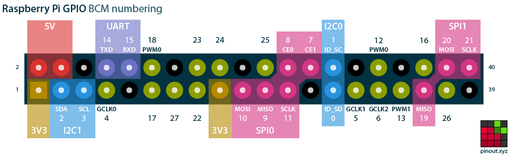
In the image, the last two pins on the bottom row on the right are what we need (you can choose another combination if you wish). Put the jumper wire that's attached on the negative end of the LED to the ground pin on the device. Next, connect the other jumper wire---the one connected to the positive leg of the LED---to BCM 26. The following image should help orient you.

Now that we have everything wired up, let's try turning the light off and on.
The first thing we'll do is alias Circuits.GPIO for convenience. If you're
not familiar with alias, see the
guides.
iex(circuits_quickstart@nerves.local)8> alias Circuits.GPIO
Circuits.GPIO
Next, we'll open GPIO 26. That's the one we put the jumper wire that leads
to the positive leg of the LED.
iex(circuits_quickstart@nerves.local)9> GPIO.open(26, :output)
{:ok, #Reference<0.1415452060.268566532.135024>}
Since that returned as expected, we can now pattern match to the ref and
assign it to led. v() runs the last command again.
iex(circuits_quickstart@nerves.local)10>  {:ok, led} = v()
{:ok, #Reference<0.1415452060.268566532.135024>}
Now we're ready to blink the light. Using write/2, we give the function the
ref for the LED and 1 which turns the light on.
iex(circuits_quickstart@nerves.local)11> GPIO.write(led, 1)
: OK
Now you should see the light illuminated.

To turn it off, use write/2 again and pass in the same ref but this time
with 0 to turn the light off.
iex(circuits_quickstart@nerves.local)12> GPIO.write(led, 0)
:ok
That's about it. You've accomplished a great deal in not a lot of time.
The Quickstart firmware contains all of the Elixir Circuits projects. By connecting other hardware to your devices, you can explore more hardware interfaces and how they're supported in Elixir. Click on the following links for more information:
At some point you may want to create your own firmware. See the Nerves Installation and Getting Started guides for details.
To build the Elixir Circuits Quickstart firmware, make sure that you have run through the Nerves installation steps. Then open a terminal window and run the following:
$ git clone https://github.com/elixir-circuits/circuits_quickstart.git
$ cd circuits_quickstart

# Set the MIX_TARGET to the desired platform (rpi0, bbb, rpi3, etc.)
$ export MIX_TARGET=rpi0
$ mix deps.get
$ mix firmware

# Insert a MicroSD card
$ mix burn