Footag is a library for automatic generation of PCB footprints.
- SMD footprints calculated in line with IPC-7351B.
- Through-hole footprints calculated in line with IPC-7251 draft 1.
- Multiple output formats
- KiCad 5.0
- Horizon EDA
- SVG, PDF and PostScript via cairo
- Your format: user-friendly output API
- Designed as a self-standing library for use in applications.
- Possibly useful for creating footprint wizards
    $ cd examples/
    $ make
    $ ./myproj
    $ ls -l myproj-out/
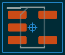
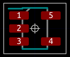
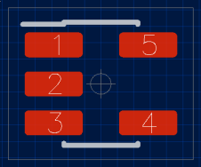
SVG (cairo), KiCad 5.0 and Horizon files are created. For example:
This software was created when the author needed a set of PCB footprints for an upcoming project. There seemed to be no tool available with the following properties:
- Support for multiple output formats
- Implementation of relevant standards
- Simple to customize library parameters, such as fabrication tolerances and artwork line width.
- Extendable with new component families and output formats
- Source code available (to judge footprint quality)
- Separation between component parameters, fabrication tolerances, project policy, artistic preferences, etc.
Footag tries to answer this need.
A C99 compiler and GNU Make is required to compile the software.
Library requirements:
cairois required by the cairo output modules (SVG, PDF, PostScript).libuuidis required by the Horizon output module.
FreeBSD 11.2:
# pkg install cairo e2fsprogs-libuuid gmake
Centos 7.4:
# yum install cairo-devel libuuid-devel
These are the main software components of the library. The name is also the linker symbol prefix.
footag_: user description of component properties and library policy.foot_: performs calculations and generates geometry in an intermediate representation independent of the output format.geom_: intermediate footprint representation.fout_: API for transforminggeomto EDA specific output format.
This is the application interface to the library. A footprint is constructed from a set of parameters, named tags. For a given component family, some tags are mandatory and some are optional. In addition, some tags are always optional for all component families, such as silk screen line width, grid settings and pad shape.
Each tag has a name, a type and a value. Tags are put on a list by the
user and provided to the foot interface to perform the calculations.
For more information of the footag interface and the available tags, see the
file include/footag/footag.h.
Below is an example on how to define a CHIP component. It includes the mandatory tags for a chip component.
    struct footag_item mytaglist[] = {
            { FOOTAG_FOOTYPE,       .data.i = FOOTYPE_CHIP },
            { FOOTAG_BODY_WIDTH,    .data.t = footol_auto( 1.60,  0.20) },
            { FOOTAG_BODY_LENGTH,   .data.t = footol_auto( 0.80,  0.20) },
            { FOOTAG_LEAD_LENGTH,   .data.t = footol_auto( 0.30,  0.20) },
            { FOOTAG_END, {0}},
    };
The function footol_auto() is used to create a dimension representation with
tolerances. footol_auto() can accept either a nominal value with plus/minus
parameter as in the example above, or as a (min,max) pair.
The footag interface provides tables which describe the tags that are
applicable to each supported component. This can be used by the application to
avoid explicit knowledge of which tags belong to which component family.
Access by the application is done with the function footag_getinfo(). See
include/footag/footag.h and
examples/showtags.c.
This software component performs calculations given the user tags and generates
a geom representation. Internally, the process has abstractions to allow
using component family specific calculations and policies. Artwork calculations
are separated from land pattern calculations.
If you want to extend the library with a new component family, or investigate
artwork calculations, take a look at struct foot_ops in
src/foot/foot_priv.h and how the functions are called.
The software could also be extended with support for other footprint or land
pattern standards or conventions. More generally, the foot implementation
tries to separate the following concepts:
- Land pattern calculation
- Pad shapes
- Artwork calculations
- Courtyard calculations
The following creates a foot context given the users tags and performs the
required calculations which are stored in the context.
    struct foot_ctx *foot;
    foot = foot_open(mytaglist);
    foot_calc(foot);
From the foot context, a geom context can be populated using foot_gen():
    struct foot_geom *geom;
    geom = geom_open();
    foot_gen(foot, geom);
The foot_gen() draws shapes onto the geom canvas.
The intermediate representation allows to construct footprint
graphics from a set of primitives, such as lines, circles and
pads. Note that geom layer does not perform any footprint
calculations and does not know about tags. All calculations
and tag parsing are performed by the foot interface.
Some commen operations of the geom API are:
geom_line()to create linesgeom_crect()to draw a rectangle centered at current position.geom_pad()to place a pad with caller specified properties.
fout provides a common API for transforming a geom representation to a
target output format. It iterates over the geom internal structures and calls
the output format provided operations as appropriate.
To create a footprint file using the KiCad 5.0 output module and also generate an SVG file, the following can be used:
    struct fout_ctx *fout;
    fout = fout_kicad5_open("myresc.kicad_mod");
    fout_gen(fout, geom, "RESC_1.6x0.8-deluxe");
    fout_close(fout);

    fout = fout_cairo_svg_open("myresc.svg", 3.0, 2.0, 10.0);
    fout_gen(fout, geom, "RESC_1.6x0.8-deluxe");
    fout_close(fout);
The same geom can be fed to multiple output modules as demonstrated above.
Output modules can have format specific parameters. The SVG output module
allows to set the cairo canvas dimensions and also has a scaling factor for the
users preference of SVG point to mm mapping.
A Horizon footprint (package) is a directory containing a file with the name
package.json. The directory name is provided as parameter to the function
fout_horizon_open(). The output module creates the directory, creates the
file package.json and writes the JSON data to it.
Horizon padstacks for use with the created Horizon package are available in the directory misc/horizon-padstacks.
To use the generated footprint with Horizon, copy or link the package and padstacks to a pool. For example:
    ln -s `realpath examples` $MYPOOLROOT/packages/examples
    ln -s `realpath misc/horizon-padstacks` $MYPOOLROOT/padstacks/footag
To get an idea of how and when the different operations of the fout interface
are called, the fout_trace output module can be studied. It will output
information on which functions are being called including parameters.
A good starting point when creating a new output module is to study the src/fout/kicad5.c or src/fout/cairo.c output modules.
- Support four-side land pattern (QFP, QFN).
- Improved tag value validation.
- Make the
footag_getinfo()mechanism distributed. That is, allow the component implementation itself define and validate required and optional tags. - Improve separation between artwork policy and pad calculation rules. Ideally support: "I want a SOIC footprint which uses IPC-7351B for land pattern calculations and with silkscreen layer drawn using artwork policy X".
- Create a front-end tool which parses tags in text format and creates footprint files according to the users choice.
- Investigate if ESA ECSS-Q-ST-70-12 can be used as pattern calculation policy.
Mentor Graphics has published an excellent article series on the topic of PCB footprint libraries: "PCB Design Perfection Starts in the CAD Library".
Design of the geom interface has been inspired by the
QEDA tool.


