This repo contains instructions for performing composite A/V out and power supply modification to a first-generation (1982, 4-Port) Atari 5200 game console.
The original 4-Port Atari 5200, released in 1982, draws its power from an adapter connected at the far end of a long and bulky coaxial cable. This site contains instructions on how to replace this cumbersome arrangement with a simple barrel jack on the back of the console.
Components Needed:
- 5.5 mm outer diameter / 2.1 mm inner diameter chassis mount power jack
- 470 uF electrolytic capacitor
- Atari 5200 expansion port cover plate (Optional, but pretty. 3D print one from the STL file included in this repository)
- Heat shrink tubing, rubber grommets, soldering/desoldering equipment, various lengths of wire, etc.
Disassemble the Atari 5200 and remove the motherboard from the case, and remove the RF shield from the motherboard. Be particularly careful when handling the smoked acrylic pieces, as they are ridiculously fragile and easy to break or scratch.
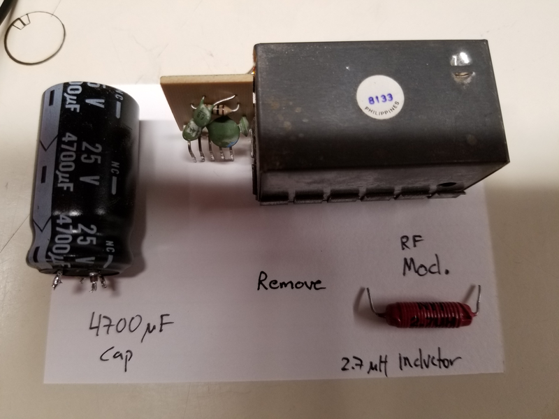
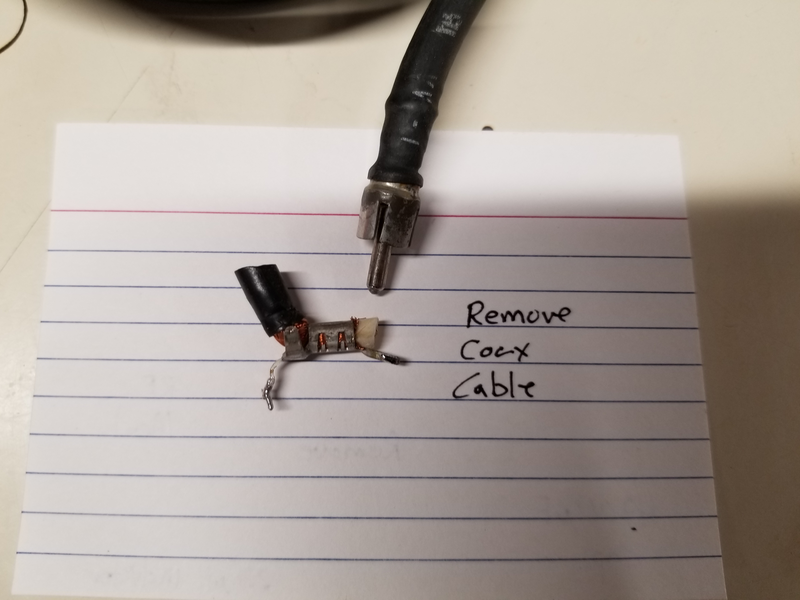
Remove the coax cable, the 4700 uF capacitor, and the inductor as shown. If you're also planning to perform the composite A/V mod, remove the RF modulator while you have the desoldering iron warmed up.
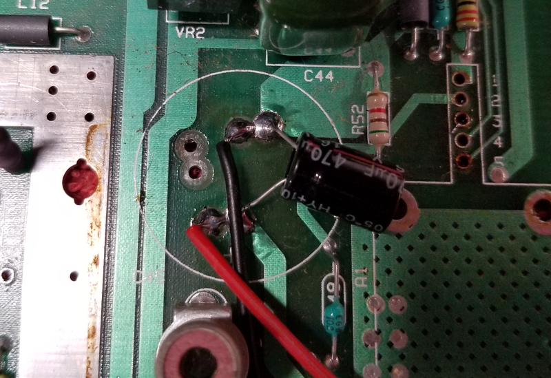
Attach the replacement 470 uF electrolytic capacitor to the same location where the 4700 uF was connected. Using the extra pads on the motherboard, solder power leads in parallel with the capacitor as shown. Make sure the power leads are long enough to comfortably reach out of the back of the case through the expansion port door.
If you are only performing the power mod, skip to step 9.
Gather the commponents needed:
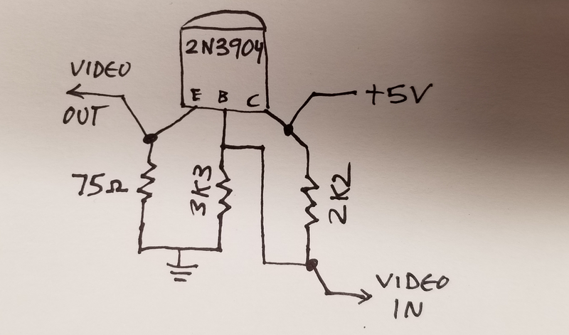
- 75R, 3K3, and two 2K2 resistors
- 2N3904 Transistor
- Perfboard
- Chassis mount RCA jacks, qty 2.
- Heat shrink tubing, rubber grommets, soldering/desoldering equipment, various lengths of wire, etc.
- Hot glue or double stick tape
Remove R33 or simply lift one side and insulate with heat shrink tubing.
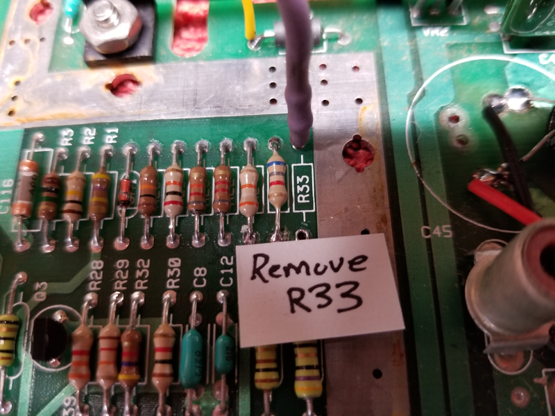
We'll need to connect four wires to the system board for the AV.
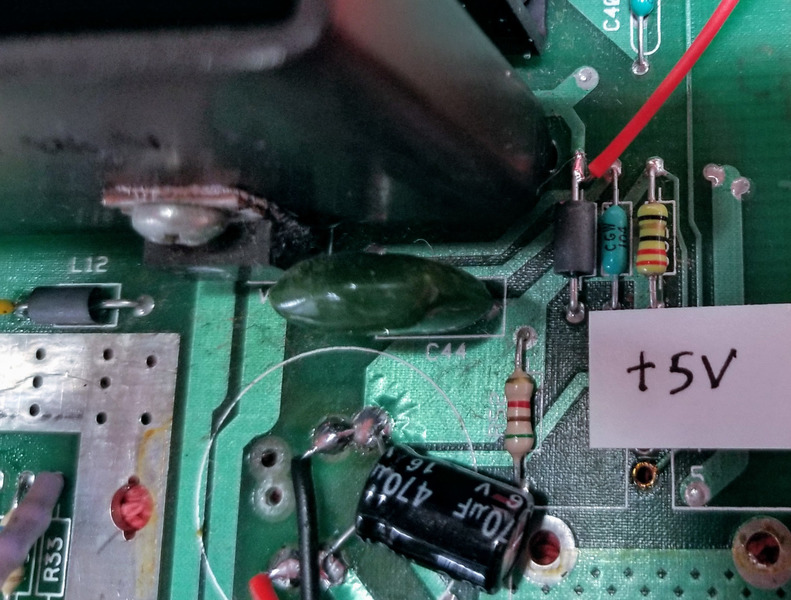
Connect a wire for +5V as shown. Leave enough length so you can comfortably route the wire to the former location of the RF modulator.
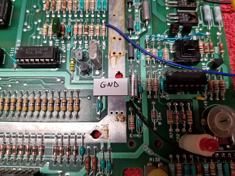
Connect a wire for ground as shown (the black cable to the lower right of the label). Leave enough length so you can comfortably route the wire to the former location of the RF modulator.
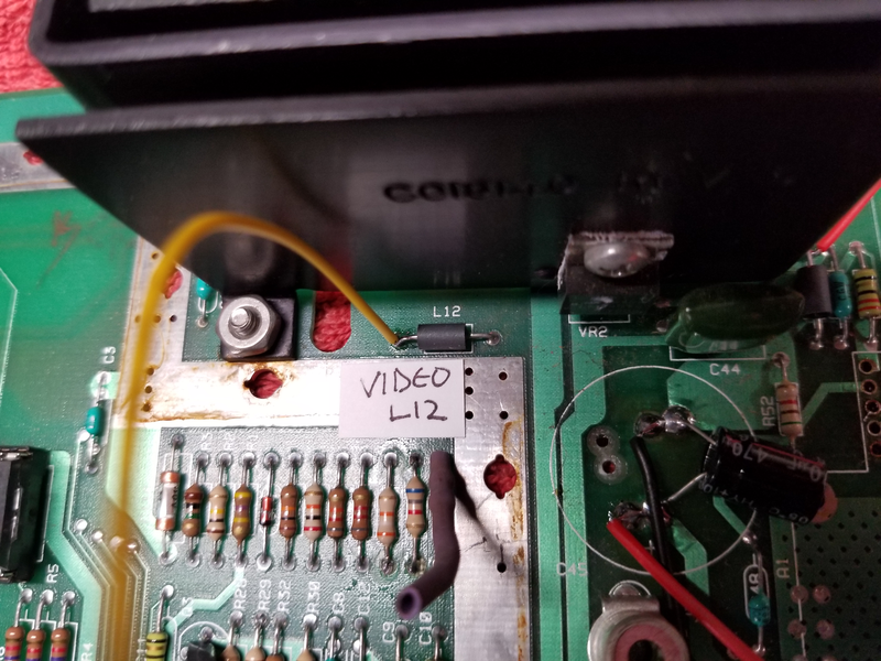
Connect a wire for video to the left of inductor L12 as shown. Leave enough length so you can comfortably route the wire to the former location of the RF modulator.
Connect a wire for audio to the top of resistor R50 as shown. Leave enough length so you can comfortably route the wire to the former location of the RF modulator.
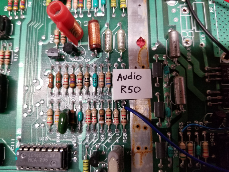
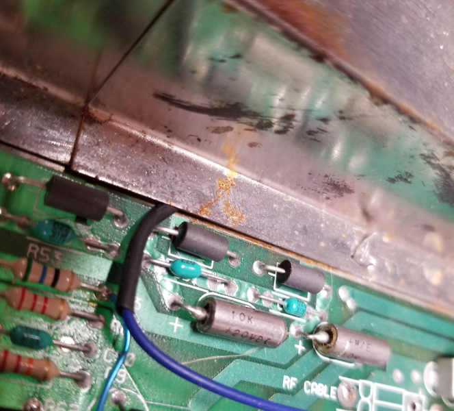
This lead will run under the RF shield after reassembly, so protect it with a piece of heat shrink as shown.
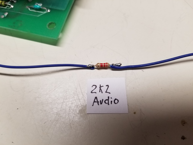
Solder a 2K2 resistor in-line with the audio lead and insulate with heat shrink tubing. This step isn't absolutely necessary, but I found that the audio sounds cleaner with an inline resistor.
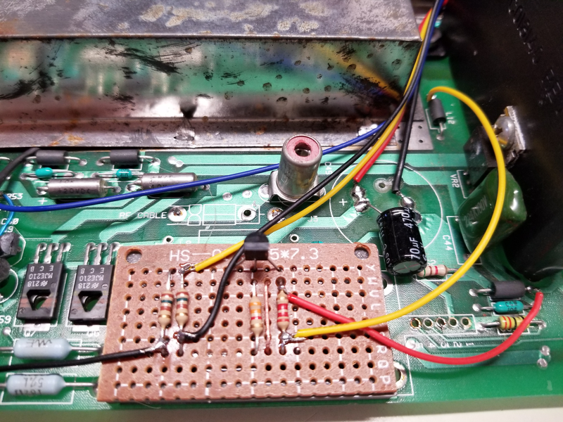
Build the transistor amplifier onto perfboard as shown.
Attach the +5V, Ground, and Video In wires to the amplifer circuit. Attach a lead to the emitter of the transistor as shown for video out, and a second lead to the ground point on the amplifier circuit to ground the A/V out jacks. These leads should be long enough so they can comfortably reach the expansion port. Attach the amplifier board to the motherboard in the former location of the RF modulator using hot glue, double stick tape, or another insulating adhesive.
Note: I was out of 75R resistors, so I used two 150R in parallel.
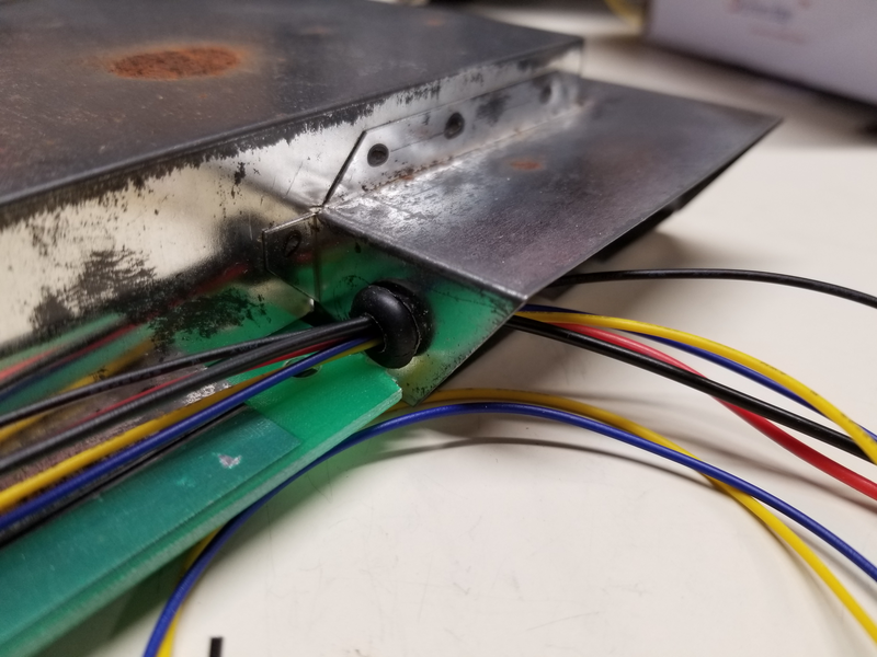
Drill a hole in the RF shield near the expansion port and run the wires as shown. Add a rubber grommet to protect the wires from the sharp edges of the sheet metal.
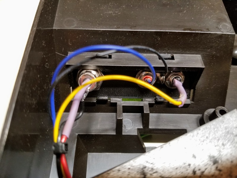
Attach the chassis mount barrel jack to the expansion port cover plate and solder the wires. The original Atari 5200 power supply is positive center, so solder the power leads accordingly.
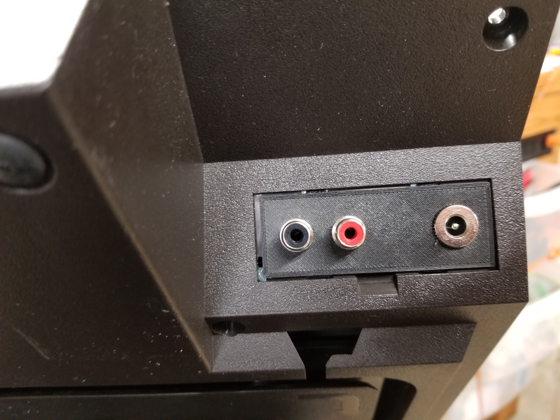
Run the power input wires (+5V and ground), the video out and ground from the amplifier board, and the audio out from the motherboard through the expansion port and out the back of the console. Attach the chassis mount RCA jacks to the expansion port cover, and then solder the audio, video, and ground leads to the jacks. Snap the new expansion port cover into the opening. Depending on the tolerances of your 3D printer, you may want to secure the cover in place with a few squirts of hot glue to prevent it snapping out of place due to the forces applied when cables are inserted and removed into the AV and power jacks.
Reassemble the console, being careful to not damage the audio wire when the RF shield is reinstalled.
Enjoy playing Dig Dug, marveling at your crystal-clear video!
