RAGE AGAINST THE RATGDO
Credit and inspiration for this work goes to @rlowens to let me know that there are other technical folks out there who needed this other than myself.
This is an open source schematic for the ratgdo, based on the v2.5 ratgdo PCB and code but installed using the ESPHome fork of ratgdo. This project was created to allow people who need a ratgdo solution for their garage door opener but either cannot, or choose not to, source the solution from Paul Wieland. It also ensures that the PCB can be recreated as and when the project maintainer gives up on the project (much like Chamberlain themselves might do with their MyQ Cloud Service) and stops selling PCBs.
You are expected to know how to create the described circuit using your own prototyping skills. That is, this project is for people who can solder well and know how to read schematics
The basic PCB schematic shown here in the Readme does not describe any circuitry other than the serial line garage door control and obstruction sensor. All other optional features provided by ratgdo can be reverse engineered as needed, or may already be solved by one of the schematics the community has uploaded!
As of January 2023, there are now multiple sources for commercially sold ratgdo boards. However if you want to buy a pre-made ratgdo setup, we recommend purchasing one from Paul Wieland so as to reward the original creator.
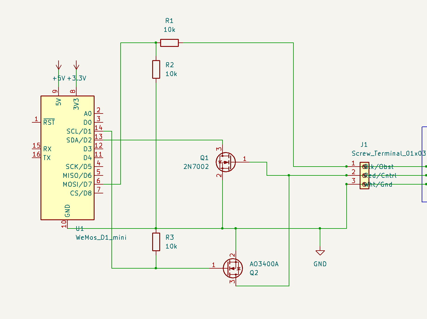
 Simple basic schematic for a Wemos D1 Mini based module
See images of a working breadboard prototype and the subsequent soldered prototype using a D1 shield. Both of these prototypes are using 2n7000 MOSFETs exclusively, but that is because they are prototypes and long term reliability of data transmission when using the 2n7000 has not been confirmed. See the section below on needed components for context.
The basic schematic shown above assumes the use of through-hole components. If you wish to use SMD components, please refer to the FAQ, and you can also check out the community-provided schematics, which include SMD-based designs.
For this basic design, aside from the obvious requirement of a supported ESP-32 or ESP8266 board flashed with the ESPHome version, you will need 3x 10 kohm (kilo-ohm) resistors, and two 2n7000 N-channel MOSFET (TO-92 package is easiest), or one 2n7000 and one AO3400A soldered to a SOT23 to DIP adapter board. It is also recommended you aquire a suitable 3-post screw terminal and some red, white, and black wire for connecting to the door opener. These connections are very low current, so you can get away with fairly thin wire.
Note: Our simple through-hole Bill Of Materials uses 2n7000 MOSFETs for both RX and TX, however depending on the manufacturere of your 2n7000 and its production batch, it might not be 100% reliable for the TX circuit. There are many examples working using the 2n7000 however, so there is a very high chance it will work.
For both this basic schematic shown here in the Readme and how they it is laid out, you must use the ESPHome fork of ratgdo and - for ESP8266 based boards - select the blue v2.5 board on the ESPhome web installer page. For ESP-32 based boards the above does not currently apply and you must use the v2.0 installer and follow our basic ESP-32 schematic we provide in the Supported Boards page.
For the ESP8266 based boards, if installing using Paul Wieland's native ratgdo installer and you install for a v2.0 board, you must wire your TX to D4 (GPIO2) rather than D1 (GPIO5).
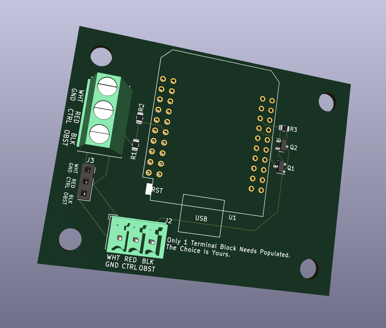
You may use the files from the schematics folder to have your own PCB printed. Shown is an example 3D render of an ESP32 based board using a Wemos ESP32 D1 board.
 An example of the D1 Mini ESP32 Wide Format
Here is an example of a printed PCB with a raw ESP8266 and an LM2596 module, for being powered by a GDO with the battery backup capabilities.
 An example of a PCB using a bare ESP8266 and LM2596 module
The community has provided a few options of schematic files suitable for sending to a PCB printing company.
- Wemos D1 Mini ESP8266
- Wemos D1 Mini ESP32 (massive overkill for ratgdo but it's your choice!)
- Wemos D1 Mini ESP32 Wide Format
- Bare ESP8266 module
If you just want to try ordering a board from somewhere like PCBWay, then check out the most recent build artifacts
The ratgdo circuitry which we cover in this project consists of two sections; Garage Door control and obstruction sensors.
The Chamberlain garage door control circuit is a two-wire setup consisting of a Ground, and a combined +12v power and serial data line. The serial data line is held at 12v unless data transmission is occurring. Data transmission is performed by pulling the 12v line down to GND for each data bit. The benefit here is that a single wire can be used for providing power to door control panels and data transmssion on a single wire. The use of appropriately sized capacitors in door control panels means they do not switch off during data transmission.
The ratgdo taps into the red control wire and uses this single wire for transmission of commands onto the serial bus, and for receiving data from the serial bus. As it is a single wire protocol and operates half-duplex, the ratgdo circuitry uses N-channel MOSFETs wired in a manner which allows the ESP8266 to never transmit when the serial line is already low.
In operation, this means that the ratgdo is mostly listening to the serial bus to ensure it is keeping track of the state of the door. For example, if the door is manually opened (or opened by use of the MyQ app even), these events are broadcast onto the serial bus by the door controller. ratgdo is therefore able to know that the state of the door has changed. In turn, this means that when controlling ratgdo via Home Assistant, the status of the door in HA is always up to date.
The ratgdo monitors the real-time state of the obstruction sensors directly. We assume this is because obstruction status is not broadcast in real time by the door controller, and safety is paramount. It allows you to set up real-time alerts in Home Assistant for any time the door is obstructed. The ratgdo taps into the obstruction sensor power wire which also acts as a communication bus, however the signalling is only an ongoing status of whether the obstruction sensors are working and whether there is an obstruction.
This is a fully open repo, in that we welcome any and all additions for all sorts of Edge Cases. If you come up with something and would like it to be available to the community, raise a Pull Request and we'll work with you to get it published!
