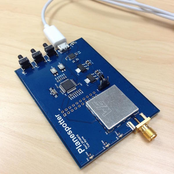
Planespotter is a side project by Tom Buttner. The goal is a small, low-cost ADS-B receiver that includes the RF front end and decoder stages. RF comes in, decoded traffic messages come out over USB.
The RF front-end on planespotter is heavily based upon the miniadsb receiver by jetvision. I'm grateful to them for being willing to sell me just one or two SAW filters. They're the best place to find the TA1090EC and TA0232A required by this design unless you're buying thousands of them.
Planespotter uses an STM32F030K6 MCU as the decoder. The STM32 family of microprocessors includes a very useful embedded bootloader, so the device can be reprogrammed over UART, elminating the need for an expensive in-system programmer. This design also includes an FT230X USB-to-Serial bridge, so the MCU can be reprogrammed right from a PC with just a binary image file.
To write a new image to the onboard flash on the STM32F030K6:
-
You may need to install FTDI's Virtual Com Port Driver if you're not on OS X.
-
Download and install Python, required for stm32loader.
-
Download and install pyserial, also required for stm32loader. If you have pip, you can just
pip install pyserial. -
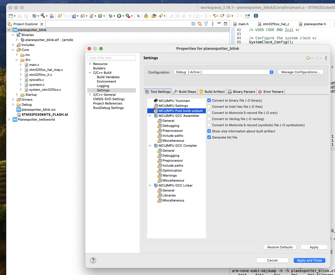
Make sure your project is generating a binary file. STM32Loader reuqires you load a binary, not an elf:

-
Plug planespotter into your PC over USB. If you're using a VM, make sure to share the FTDI USB-to-Serial Device with the VM from the host machine.
-
Find the device name for the usb-serial adapter on your planespotter:
$ ls /dev/tty.usbserial* /dev/tty.usbserial-DB00KYMI -
Place the STM32 in Device Firmware Upgrade (DFU) Mode by holding S50 (BOOT0), tapping S20 (RESET_L), and releasing S50.
-
Make sure planespotter and the binary you are flashing are in the same directory (they are, if you're using a binary provided at planespotter/software/).
-
Use stm32loader to load the binary onto Planespotter:
$ ./stm32loader.py -e -w -v -p /dev/tty.usbserial-DB00KYMI -b 57600 <image_name> Bootloader version 31 Chip id: 0x444 (Unknown) Extended erase (0x44), this can take ten seconds or more Writing: 100% Time: 0:00:13 |#################################################| Reading: 100%, Time: 0:00:07 |################################################| Verification OK -
When programming has finished, tap the Reset button (S20).
-
Planespotter will talk over the same serial port you just used to program it as soon as it comes out of reset. Baud is 115200, no flow control. Fire up your favorite terminal emulator or use screen:
screen dev/tty.usbserial-DB00KYMI 115200
Firmware for this project will be posted here as it is developed. This project doesn't have working ADS-B detector software yet as I wasn't able to located a signal with any of the crappy antennas I already have and I'm trying to get my hands on a signal generator to prove out the detector.
Firmware is probably going to have to be in assembly in order to provide the speed required to decode the 1 Mbps PPM ADS-B signal from the (missing) hardware comparator.
Prior to discovering assembly was likely a requirement, but after much messing around with Keil and STM32Cube, I did initial bringup and some tests with the mbed platform. This is a really handy way to work with this processor if you're not trying to shoehorn something into it like I now am.
To use the mbed online compiler, go to https://developer.mbed.org/compiler. Planespotter bringup firmware was built using the NUCLEO-F031K6 target in the mbed compiler, which is effectively just a breakout board for the STM32F031. This is close enough to write software for Planespotter.
To grab the full mbed project I was using for bringup, use the mbed compiler and pick up the project from its Mercurial Repository.
For the actual files used to produce fabricated boards, see the releases folder. Every release will include a schematic PDF, Bill of Materials (BOM), and set of Gerber files used to fab the PCB.
| Problem | Fix | Notes |
|---|---|---|
| Allow onboard FTDI to toggle BOOT0 for easier target programming | ||
| Add labels to S20 and S50, J50 | ||
| Mark optional matching network more clearly and mark 0Ω resistors as "DNP" | ||
| Analog sampling isn't fast enough for 1 Mbps PPM ADS-B | Add external hardware comparator to generate a logic-level PPM signal, or switch to a micro with a built-in comparator |
(I go long periods of time without messing with this thing).
- The RF Front-End works! Proved out with a Telemakus TEG4000-1 signal generator and some attenuators on 4/2/18.
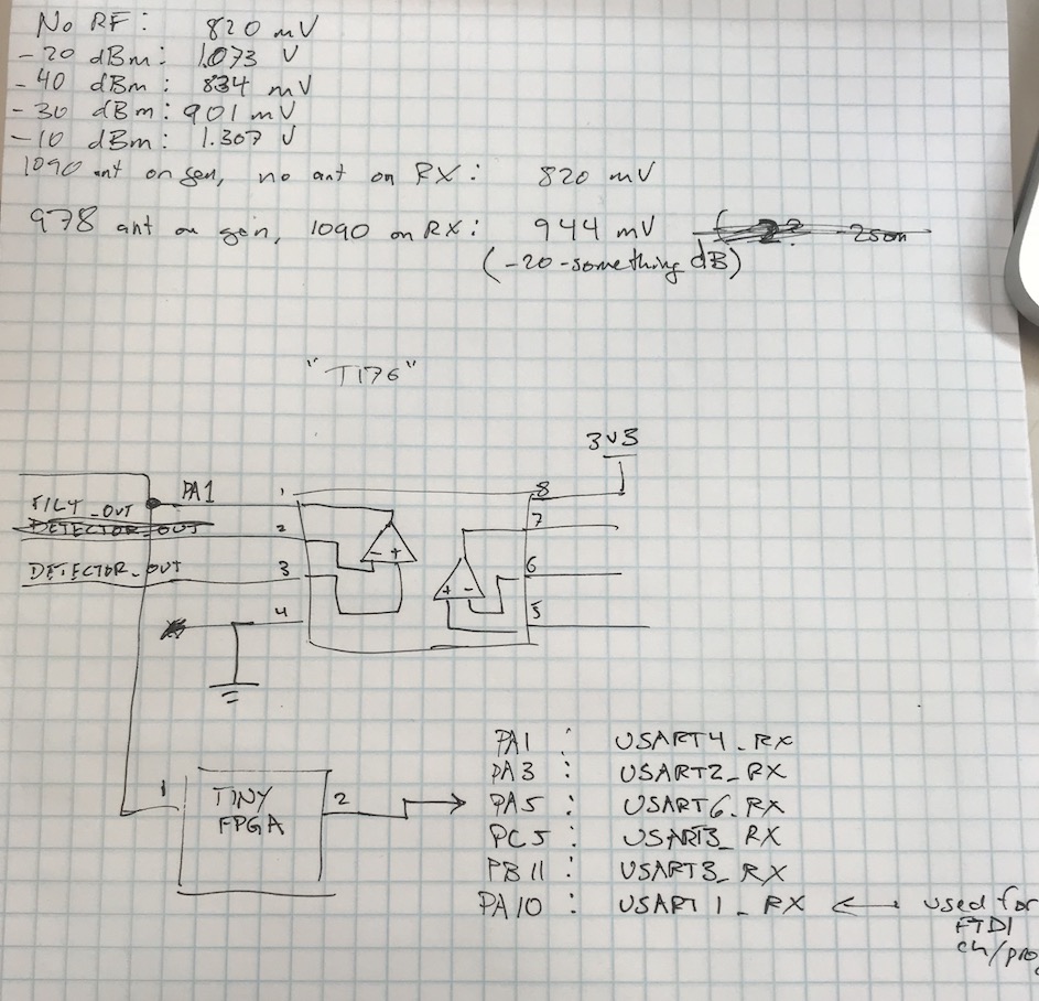
- Added a comparator and it works too! Verified 4/2/18. Notes and schematic snippet:
- Added a TinyFPGA A1 to my Rev01 prototype as an option for ADS-B decoding; could just send UART info to the STM. Although at that point there's not much point in not just sending it to the USB Host to be plotted or posted to an online service - if the FPGA decoder works out, probably want to switch to an imp for a standalone receiver.
- Tests with mbed Ticker locked the processor up when run faster than 100 kHz.
- (10/22/24) Six years later...
- I don't know that I really need the FPGA for anything here, the STM32F030K should be able to run its clock up to 48 MHz. ADS-B bitrate is 1 MHz. Brute-force decoding the PPM input with interrupts requires 500ns (2 MHz) precision, which should be fine. This resource is super helpful
- mbed is being retired. I think my next move should be to stand a hello world back up for the STM32F030 using STM32Cube. These example projects may help.
- (10/28/24) Put a blinky image on my prototype with STM32CubeIDE, so I'm ready to get back to firmware. Added notes on configuring project and using the STM32Loader.
All material in this repository (unless otherwise specificed in the file) is licensed under the MIT License.
See LICENSE.md for more information.

