Starting with Oscar's KIM-UNO code, I changed out the 6502 for an 1802. See: http://obsolescence.wixsite.com/obsolescence/kim-uno-summary-c1uuh for more details.
v2:
- Updated: Removed platformio! The USB serial port was unreliable in subtle ways when pushing a lot of data. With the Arduino library it seems fine. Rather than troubleshoot it...
- Moved back to platformio. Should still build with Arduino IDE. Note: when using pio, leaving DFU mode doesn't work. You must turn off the bootloader and reset to run code. Not sure why.
v1:
- Blackpill target
You have 32K of RAM at 0000 and no interrupts. There is a 32K ROM at 8000 To change the ROM you must reflash the Arduino
The ROM installed is the STG ELF2K ROM which has Basic, Forth, an assembler, and a debugger along with other tools.
To run it put C0 XX 00 at location 0 to jump to it (where XX is 80 for for IDIOT/4, 90 for ETOPS, and C0 for Hi lo). On power up (but not reset) the first 3 bytes of RAM initialize to C0 80 00.
The file 1802rom.h only includes other files so it is reasonably easy to flip different ROM images around and change where they load. Note that 1802 code is not always relocatable, so be sure you put ROM code where it will run correctly.
The blackpill version, so far, does NOT support the Kim UNO hardware. You must operate via serial port. There are two modes selected by PB2. If PB2 is low, the serial terminal is just a terminal (no front panel mode; see below) and the ROM at 8000 executes. If it is high, you will be in front panel mode (see below). To boot the ROM in front panel mode and flip the terminal, enter: G| (just two characters). Note that with the included ROM, executing SHOW CPU will trigger a breakpoint to the meta monitor (see below).
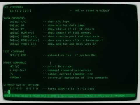
If you have a serial terminal (e.g., a PC running a terminal program) you can use it in one of three modes. First--the default--is front panel mode. Keys on the terminal map to keys on the keyboard (e.g., G is GO, R is RS). There are also commands for dumping memory, loading memory, etc.
If you use the | command from front panel mode, the serial terminal will become a normal serial terminal your program can read and will no longer operate as a front panel. This will continue until the Arduino resets (an 1802 reset isn't sufficient) or until a power cycle. This is useful for terminal-oriented programs like IDIOT/4.
While in front panel mode you can also press \ to enter the meta-monitor. This allows you to perform a lot of functions from the terminal. Note that while front panel commands don't work while in this mode, you can send the front panel a command using the "." command (that is, .R is reset, .? dumps memory, etc.). When running the included ROM, entering SHOW CPU will also enter the monitor. To resume from that, issue: R3=8BEE and then C.
Using the keypad to load programs is a bit tedious. If you have a program already entered you can save it to EEPROM and later restore it using the keyboard or the terminal. In addition, the terminal can read a simplified hex format or Intel hex format files. It can also dump memory in both of those formats. To save RAM to EEPROM hold down SST for one second or use the > terminal command. Reverse the operation by holding down AD for 1 second or using the < command.
This only works on the first 1K of memory and is not recommended!
The keyboard doesn't exist, but it is mapped like this:
- Go - Run
- ST - Stop running or stop load mode
- RS - Reset
- AD - Copy extended data register to load address
- + - EF4 (Input key for program or load mode enter)
- DA - While idle, enter load mode
- PC - Protect memory toggle so that load mode displays data
- SST - Single step
- 0-F - Build up hex number. Accumulates 16-bits although you can only see the lower 8. For load mode, the lower 8 is used. For AD all 16-bits are used.
- DA - Hold down for one second to save RAM to EEPROM
- AD - Hold down for one second when not running and not memory protected to read RAM from EEPROM
On a terminal (9600 8 N 1) you can use normal keys like 0-9 A-F a-f and these additional keys:
- ST=S
- RS=R
- AD=Equal sign (=)
- DA=L
- GO=G
- PC=P
- SST=/
- DA (1 sec)=<
- AD (1 sec)=>
Note: + does not act as Enter from the terminal; use $ to toggle EF4 instead.
That means that like KIM UNO, you don't need the hardware to run it (well, you do need the Arduino).
- | - Go into serial terminal mode (until power cycle)
- ; - Toggle trace mode (warning: makes execution slow). Prints address, opcode, and D on each instruction execution
- * - Dump registers and state
- ! - Dump address and data displays to terminal
- ? - Dump 1K of RAM in 1802UNO Format (see below)
- $ - Set EF4 on/off (overrides HW keyboard)
- @ - Load RAM in 1802UNO Format (see below and examples directory; also see binto1802.c)
- X - Load RAM from Intel hex file
- Y - Write 1K RAM to Intel hex file (hint, you can delete all the zero lines and keep the last EOF line using a text editor)
- \ - Enter monitor mode. This is a meta-monitor running in the host Arduino. See section below for more details
Remember, you can issue any of these commands from the meta-monitor by using a period. So .; toggles tracing or .! shows the displays.
In addition, you can write to the terminal from 1802 code at port 1. If you want to read from the terminal, you can enter a | character. Once you do, the terminal will not act as a front panel anymore.
The 1802 code can control that mode by writing a 1 to port 7 to disable the serial front panel. A zero will reenable it.
In addition, there is support for a large amount of Mike Riley's ELF BIOS.
With a serial port connected, you can send the ? command to get a dump of all 1K of memory.
You can also set memory by sending back the string returned by the ? command. You can also make your own string using the following format:
@address:byte byte byte byte .
Everything is in ASCII, so "@0000:7A 7B ." is 13 bytes. Note that you don't need all the digits (e.g., "@0:5 2 1 FF ." is OK. Also you must have a space betwween bytes and before the period which ends the transmission. The only characters that matter are the @ sign, the period, and the hex digits (upper or lower case). So you could just as well say "@0000=7a,7b&." if you wanted to.
You can also read and write Intel hex files with X and Y commands. Note that Y writes out all 1K of RAM. The last line is an EOF record and you can delete any lines you don't care about. So if you dump a simple program that takes, say, 30 bytes, you can keep the first two lines and the last line and delete the rest using a text editor.
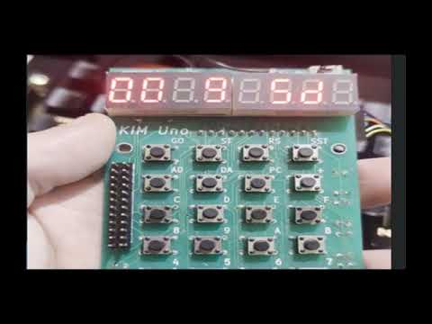
On the original KIM UNO hardware we have the following LEDs.
    +--------+--------+--------+---------+---+---------+-------+
    | LED1   | LED2   | LED3   |  LED4   |   |  LED5   |  LED6 |
    +--------+--------+--------+---------+---+---------+-------+
    |    . Q |  . LOAD|  . RUN |   . EF4 |   |   . PROT|       |
    |        |   STATE|  STATE |         |   |     MEM |       |
    +--------+--------+--------+---------+---+---------+-------+
(Thanks for the graphic Oscar)
The only LEDs on the Blackpill version is the Q LED on PC13.
- The BIOS is lightly tested and may not have all the same private semantics as compatible BIOS
- Who knows? An SD card maybe? 1861 graphics? Banked memory or ROMs?
http://hackaday.com/2017/07/25/kim-1-to-cosmac-elf-conversion-sort-of/
- Port 1 - Serial port
- Port 2 - LSD of address display (if enabled)
- Port 3 - MSD of address display (if enabled)
- Port 4 - Switch/Data LED
- Port 7 - Control port. Set bit 0 to disable serial front panel. Set bit 1 to put address displays under program control (see port 2,3).
There is experimental support for a small number of BIOS function when BIOS=1 (see 1802config.h). These BIOS calls are not written in 1802 but are handled by the Arduino host. The baud rate is fixed so any BIOS function that in the "standard" BIOS that takes a baud rate value will ignore it. Other than a 1 sets the echo flag.
To use the BIOS you must set up SCRT:
- 0xFF3F - Set up SCRT. Put a return address in R6 and do a LBR to this address. On return, P=3 at your return address. R4 will be set up to do an SCRT call and R5 will be set up to do an SCRT return.
In addition, the SCRT routines use the non-standard addresses 0xFF01 and 0xFF02. Since this is set up by 0xFF3F, even if they change, you should not notice.
Note that when stepping "through" a BIOS call, you will see a bogus instruction fetch, but the operation should complete as intended.
- 0xFF2d - Baud rate call, does nothing since we do not support multiple baud rates
- 0xFF03 - Send character in D to terminal and translate 0xC to 0x1B.
- 0xFF43 - Send character in D to terminal (no translation)
- 0xFF06 - Read terminal character into D
- 0xFF09 - Print null-terminated string pointed to by RF
- 0xFF81 - Return capability word in RF (we return 8 for supporting a UART)
- 0xFF0F - Read up to 255 characters (plus terminating null) from terminal. Buffer in RF (unchanged)
- 0xFF69 - Same as 0xFF0F but count is in RC
- 0xFF12 - Compare string @RF with string @RD, D=00 for equal, D=FF for < and D=01 for >
- 0xFF15 - String pointed to by RF, set RF to first non space character
- 0xFF18 - Copy string from [RF] to [RD]
- 0xFF1B - Copy bytes from [RF] to [RD] for count RC
A few more have been added to suppor the STG ROM, see 1802bios.cpp
Platform IO was used originally but with the blackpill it is a problem to make the USB serial work reliably with it. So the blackpill version uses the Arduino IDE with these settings:
- Board: STM32 MCU Based Boards | Generic STM32F4 series
- Board Part Number: Blackpill F401CC
- C Runtime: Newlib Nano (default)
- USB Support: CDC (generic SERIAL supersede USART)
- USART Support: Enabled (generic SERIAL)
- USB Speed: Low/Full Speed
Enter Monitor mode with the \ key while in front panel mode. You do NOT have to switch the keyboard using the | character. Note the keyboard and display will be dead while the monitor is active.
Upper/lower case does not matter. Note that backspace sort of works, except on multi-line M commands. Even then, it works, just with a twist (see the M command for more). You can use Escape to abort a line. Esc will also abort a long memory dump.
You can #define MONITOR 0 in 1802config.h if you want to disable it.
Note: lower case letters represent numbers
- B - List all breakpoints
- B n - List breakpoint n (0-F)
- B n - - (that's a dash after the number) Disable breakpoint n
- B n @aaaa - Break at address a, breakpoint n
- B n Pp - Break when P becomes equal to p
- B n Iii - Break when current instruction is ii
- C - Continue execution (assuming 1802 is running; same as Q)
- G aaaa - Goto address
- G aaaa p - Set P to p and goto address
- I n - Input from port n
- M aaaa - Display 256 bytes from address aaaa
- M aaaa nnn - Display nnn bytes from address aaaa
- M aaaa=nn nn nn; - Set bytes starting at aaaa (multiple lines allowed with semicolon only on last line; see notes below)
- N - Execute next instruction
- O n bb - Output byte bb to port n
- Q - Quit. Will resume execution if 1802 is running.
- R - Display all registers
- R n - Display register N (note 10 and above are special registers, see below.
- R n=vvvv - Set register n to value vvvv
- X - Exit. This will not resume execution.
- . - Dot command. Sends next characters to the front panel simulation. That is, .$ toggles EF4. .41$ enters the number 41 on the keypad and presses (but does not release) EF4
- ? - Very basic help message
In addition to working with registers 0-F, you can access other registers using numbers larger than 0F.
R0:8042	R1:00FF
R2:00FE	R3:0002
R4:80F0	R5:800B
R6:8064	R7:00FD
R8:0000	R9:0000
RA:0000	RB:0000
RC:0000	RD:0000
RE:0000	RF:0000
(10) X:7	(11) P:6
(12) D:0B	(13) DF:0
(14) Q:0	(15) T:0
Note that R12 is the accumulator "D" not register D. You can see the list by using the R command.
Note, too, that the parens mess up the GitHub markdown formatting, but escaping them doesn't work either (actually, it fixes the formatting but the \ characaters appear in the text).
R2=AA - Set register 2 to AA


M 400 - Display 100 hex bytes at 400
M 400 10 - Display 10 hex bytes at 400
M 400=20 30 40; - Set data starting at 400 (end with semicolon)

G 400 - Goto 400
G 400 3 - Goto 400 with P=3

BF I7A - Set breakpoint when instruction 7A executes

I 2 - Show input from N=2
O 1 41 - Write 41 to output N=2 (this will echo on terminal)
For fun while playing HiLo, try this (from front panel mode; if already in the metamonitor, you can skip the \ input):
\
O 7 2
o 2 14
o 3 07
c
Now look at your 1802 UNO upside down!
You can enter new bytes on one line: M 400=7A 7b 30 00;
Note that there is a limit on line size (currently 31 characters).
However, if you start a new line (you get a colon prompt), you will not be able to backspace past the current byte:
M 400=
0400: 20 30 40
0403: 50 60 70;
Backing up while entering 30 can only delete the 30 and not the 20. Also, instead of backing up you can just keep going as in:
:M 400=
0400: 200 300 400;
All 3 bytes will then be zero. Note that if you start entering a byte, you will overwrite that byte even if you backspace it out (it will write as a zero).
The dot command is pretty handy. For example:
.44!
Will set the data input (port 4) to 44 and then display the address and data LEDs on the terminal.
.; is also useful (set/reset trace mode)
For example, try this:
.5A I 4
You'll see that the input reads 5A, as set.
Code a 68 (an illegal 1802 instruction) to force a jump to the built-in monitor.
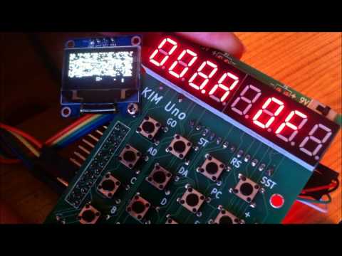
Note: This video shows the "Pixie" branch code with the OLED but the base code is the same as this branch.
If you are having trouble with using the serial port, this might help: