HALO-90
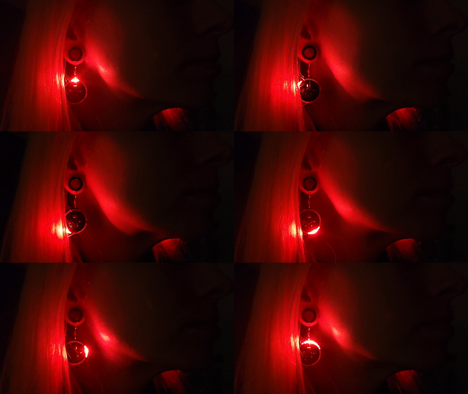
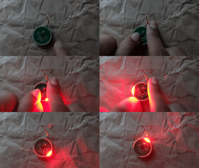
A distinct ring of light. An ethereal glow. Patterns that ebb and flow to the music. Ninety lights. All controllable. Powered by a common coin cell. An engrossing look with retro vibes and a modern touch. This is HALO-90.
The HALO product series, in which these earrings (HALO-90) are the first item, is a fully open source electronic jewelery line. It is designed with elegance and wearability in mind. 90 refers to the ninety individually controllable LEDs on the earring face. The built-in compute power is also suitable for creating complex light shows.
This is the technical manual for anyone wanting to modify, hack, remix, or program their own light patterns onto the earrings. The manual goes into fine detail about construction, assembly, and firmware which should encompass all basic knowledge.
Table of Contents
- Design
- Firmware
- Absolute Maximum Ratings
- Guaranteed Ratings
- Manufacturing
- Programmer
- Artwork
- Inventory and QC
- Packaging
- Shipping
- Safety
- Certifications
- Licence
- Attribution
- ToDo
Design
Design was always a core objective from the very beginning. It has to look good. Even more importantly, it must also be functional, as it is a piece of jewelery people are going to wear. If it looks too complex or it's too difficult to use, no one will want to wear it. Comfort was also major goal, as heavy earrings are painful to wear for extended amounts of time, no matter how stunning they are. It's simply not worth the pain.
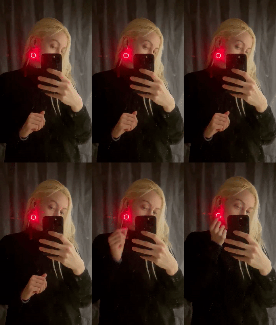
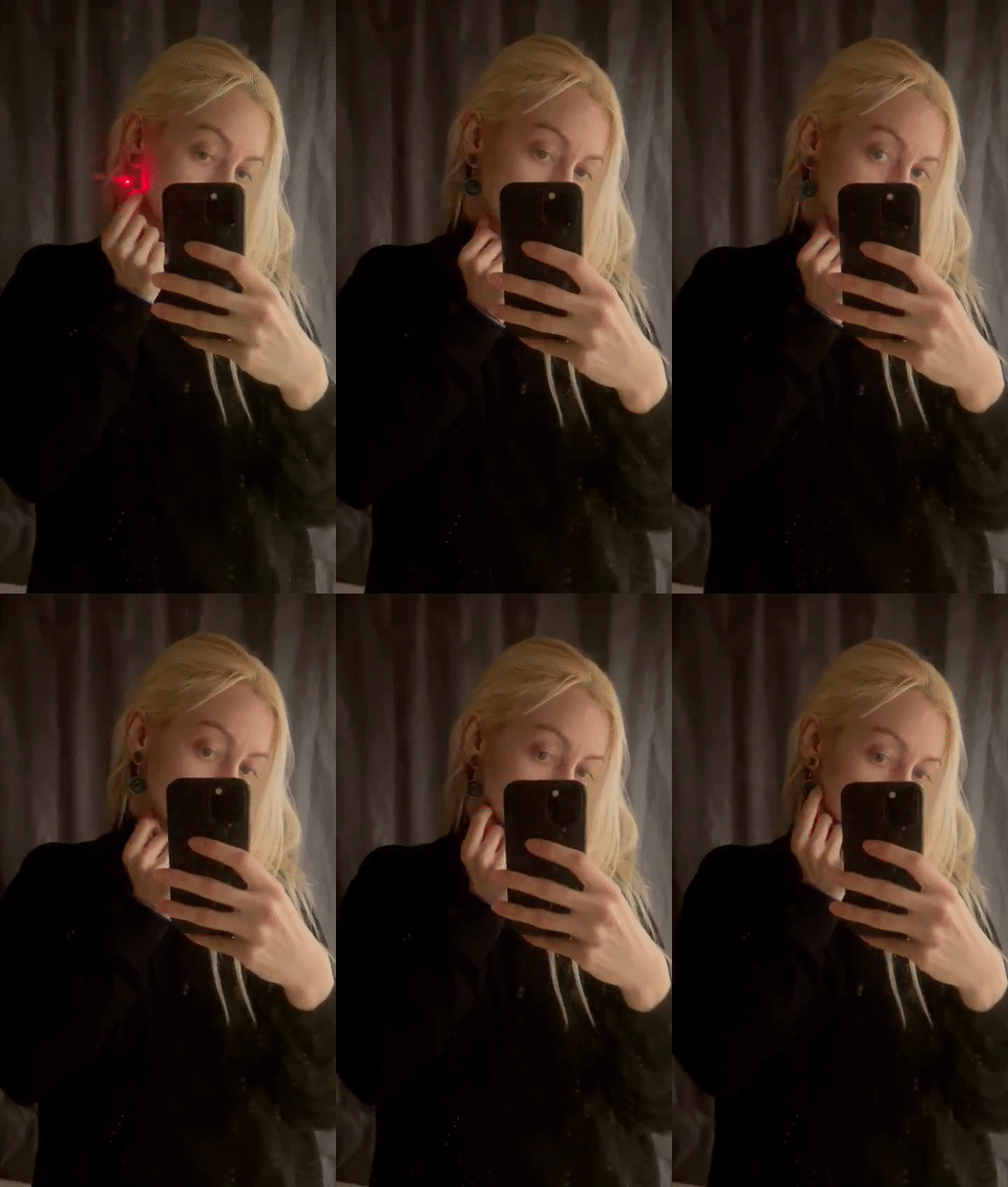
The design had to allow for a variety of LED patterns with a range from subtle to attention grabbing. Sensors were added to make light patterns more personal and reactive to the local environment, such as the muted audio responsive pattern. At one moment, befit for a quiet restaurant and later a flashy wide pattern at a concert.
| Audio | Halo | Sparkle |
|---|---|---|
 |
 |
 |
Hardware
The electronics are kept minimal for cost reduction and manufacturing simplicity with pads and routing done for all but the IMU and its pullup resistors. They are not mounted, because there is no firmware support for that and it yields a lower cost variant. The design is done in KiCad 5.99 (nightly) and will be ported and set in the stable version. All components and libaries are embedded in the project.
The schematic is also available as a pdf. The layout is done partially programatically using text manipulation and template stamping using javascript and node and then finished up by hand in KiCad. The code is available here.
LEDs
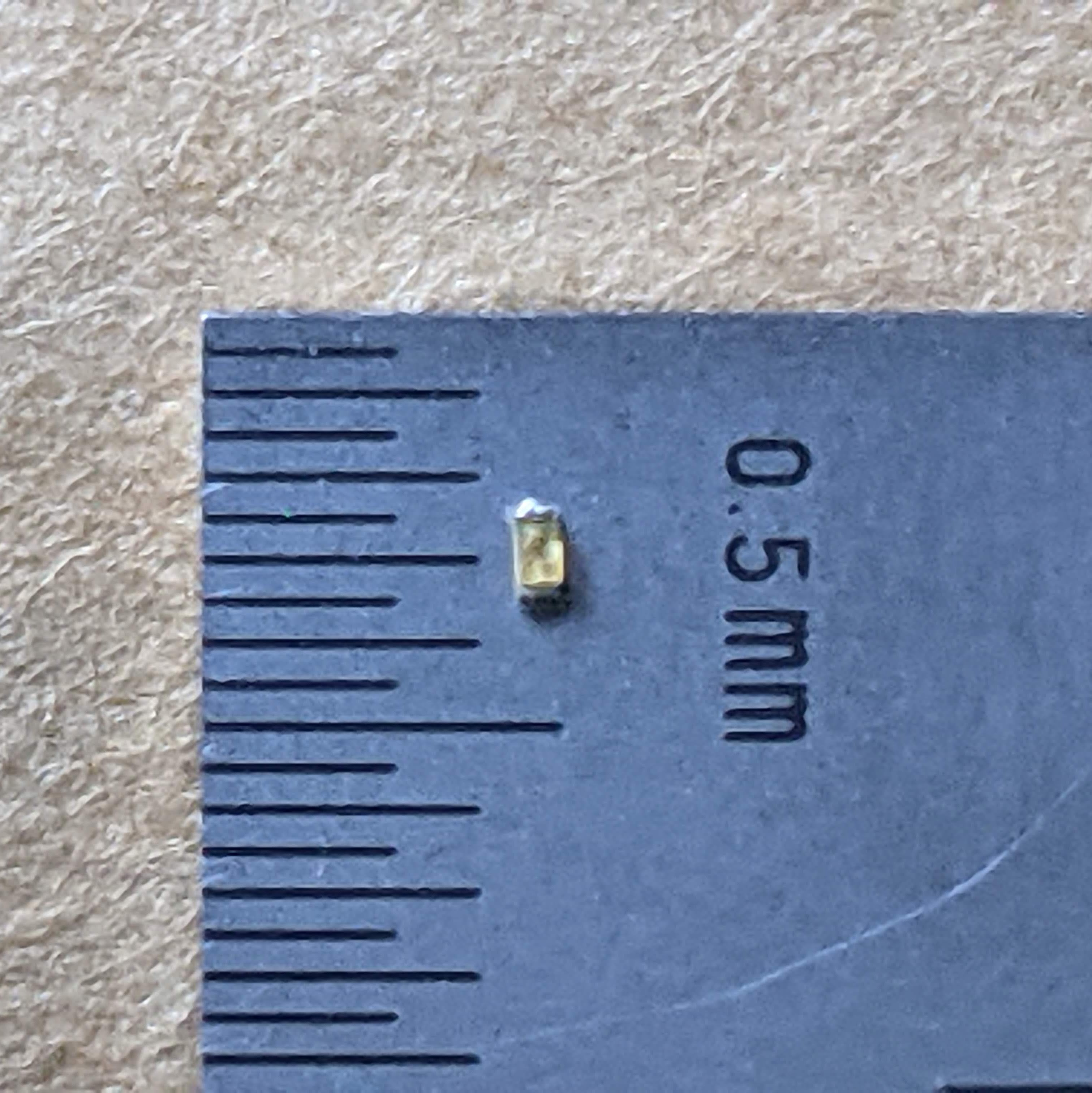
There are 90 LEDs that make up the ring, All are regular 0402 red diodes. All the cathodes (K/-) face towards the center of the board, and are placed at 4° intervals. The LEDS are charlieplexed with ten lines providing individual control. They are run at as high of a current as the battery's internal resistance and GPIO max current allows, so no resistors are used. The red LEDs, with their 2.0 V - 2.6 V forward voltage, permits maximizing battery usage
We are using BL-HUB37A-AV-TRB, because it is low cost and has high availabilty across multiple vendors in China, but any 0402 LED with a Vf below 2.7 V, should yield an equivalent battery life.
Microcontroller
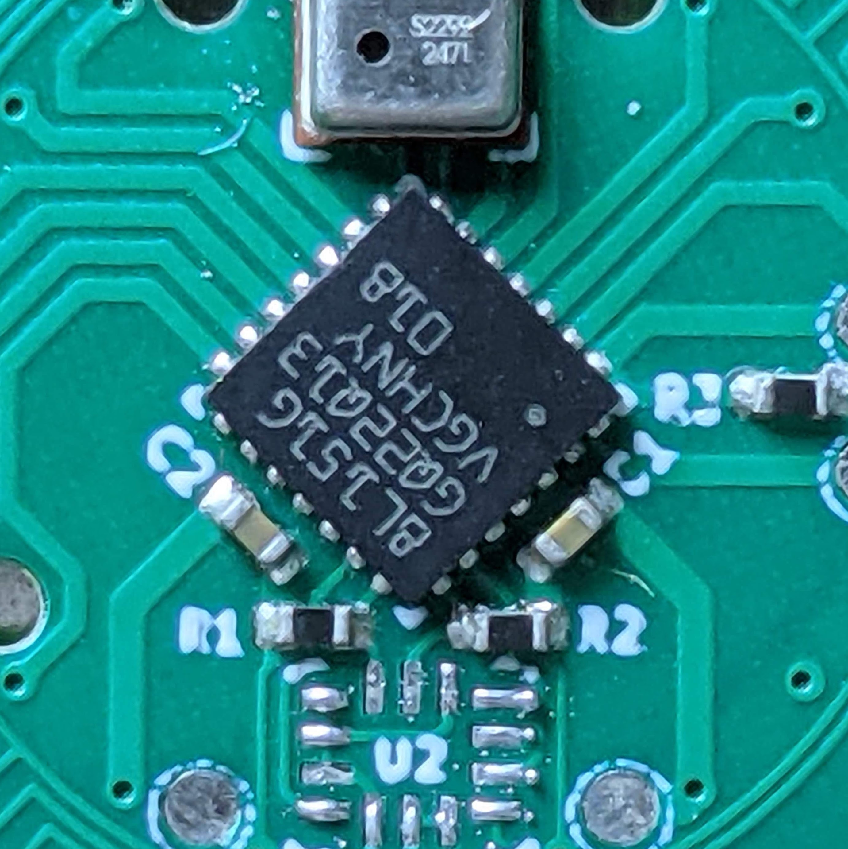
STMicroelectonics's STM8L151G4 acts as the main controller for the earring. The low power microcontroller has a wide range of peripherals, a long expected production life, and low cost and availability in high quantities. Running at its max speed of 16 MHz is able to easily charliplex the 90 Leds at over 1 kHz. The 12b ADC is used to readout the microphone and has plenty of flash (up to 32k) to store an assortment of light patterns or complex processed designs.
Battery
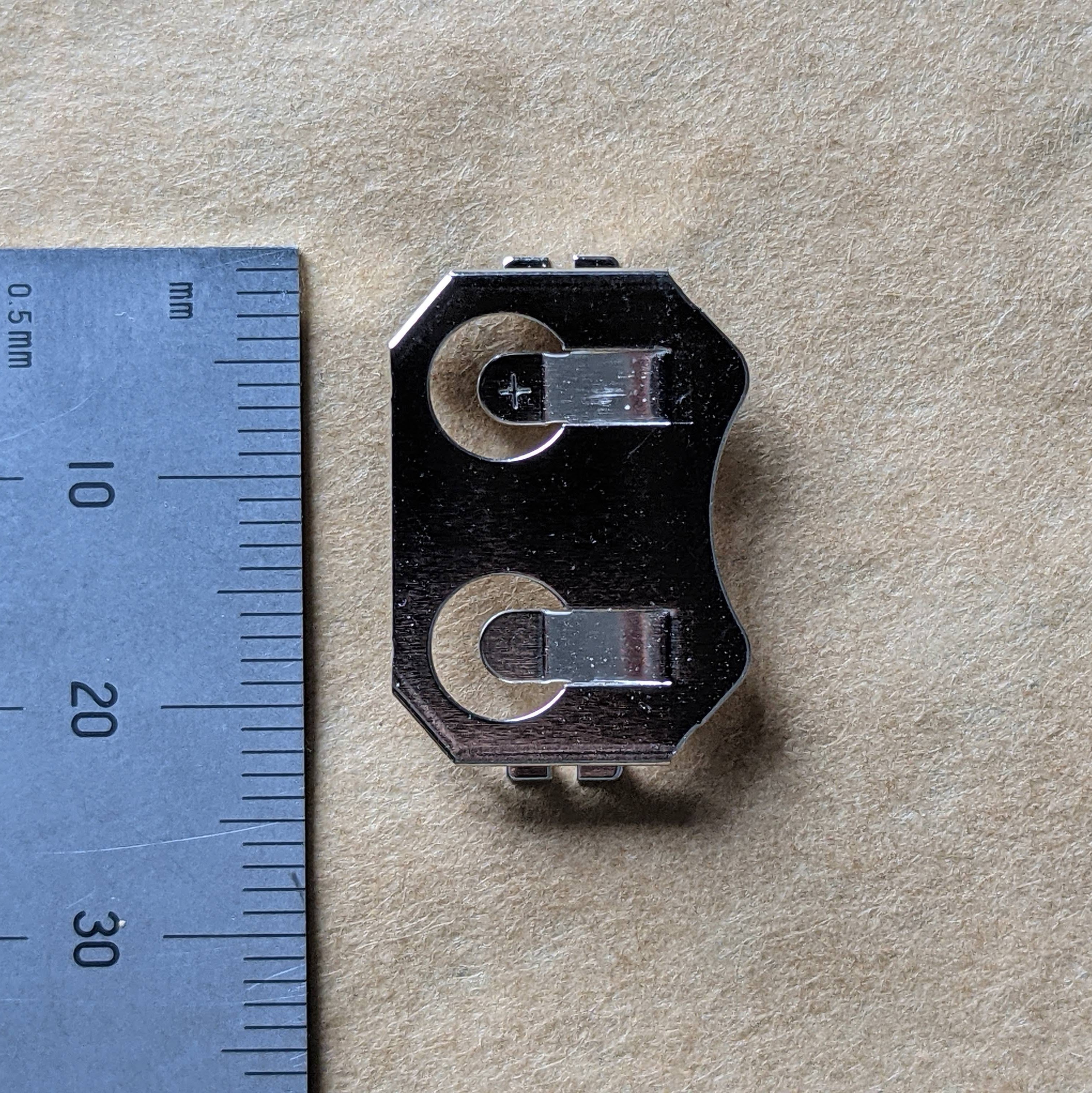
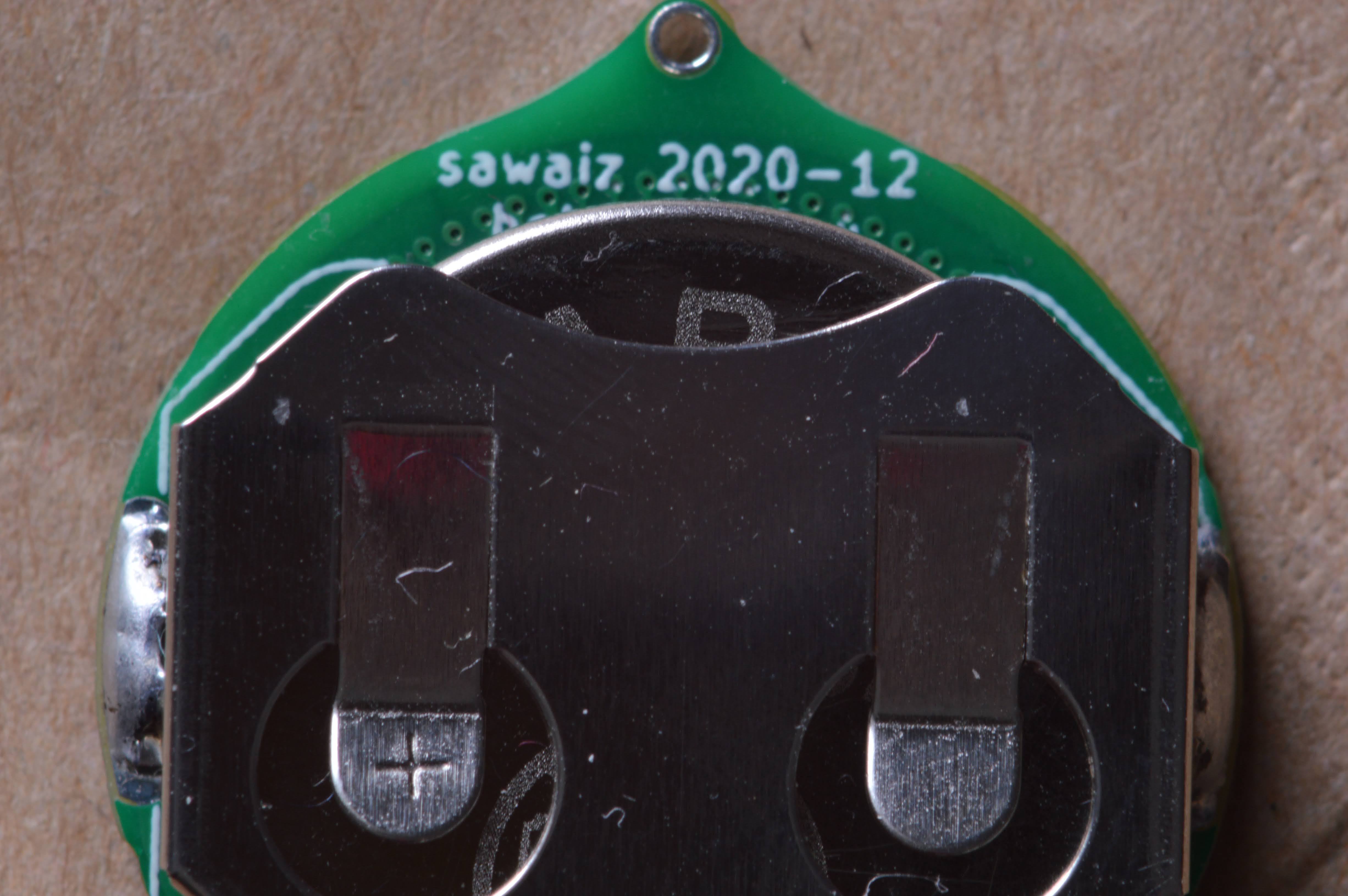
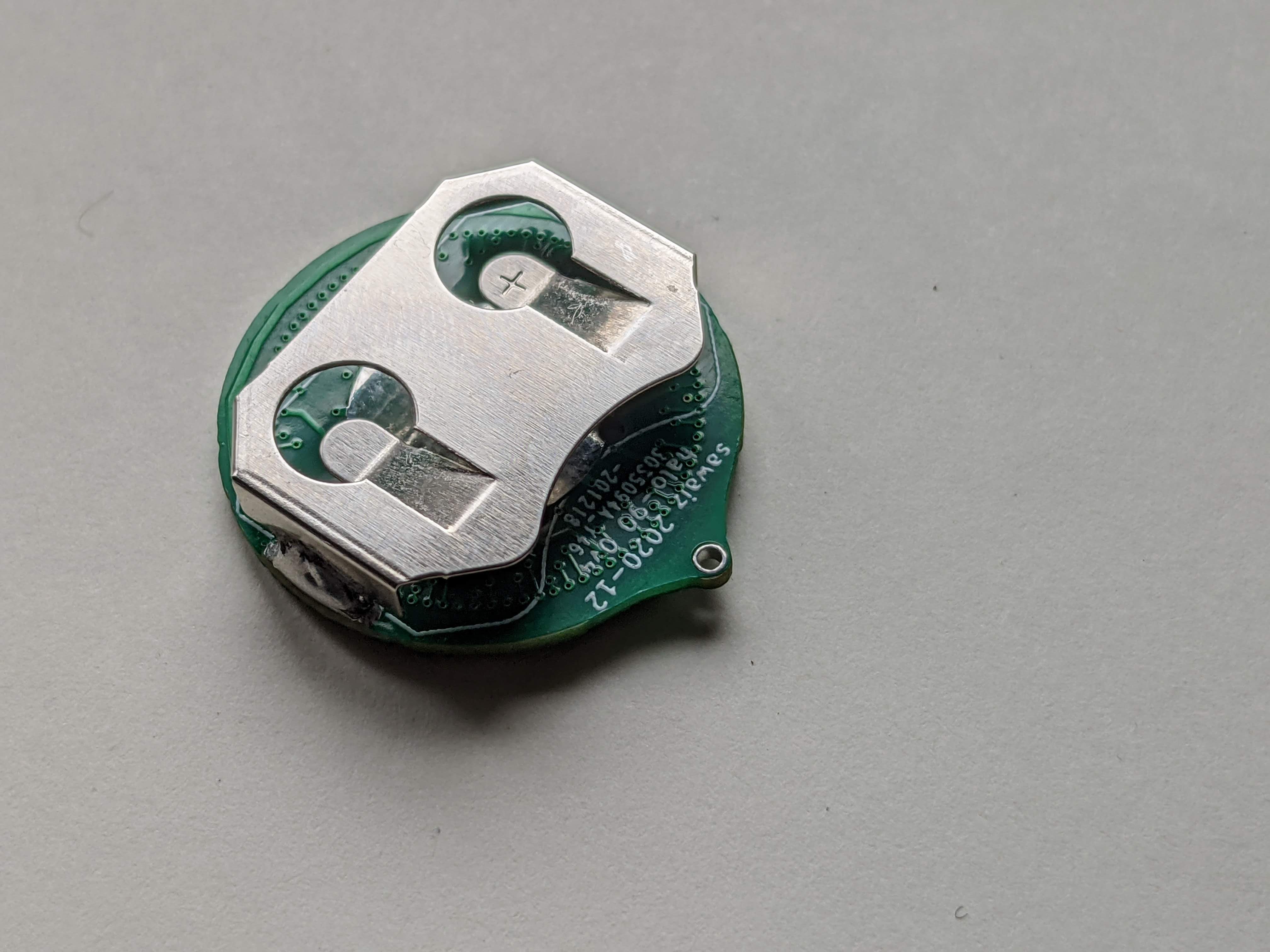
Linx Technologies's aptly named BAT-HLD-001 is a stamped die-cut sheet-metal battery-holder that is as low profile as possible. It is sized for a CR2032 lithium cell. The metal acts as the anode while the pad on the PCB is the cathode. Battery life varies based on what threshold for brightness you are content with. Over its lifetime, the internal resistance of the battery increases and the voltage decreases. This means that the current possible also decreases and thus the brightness.
Microphone
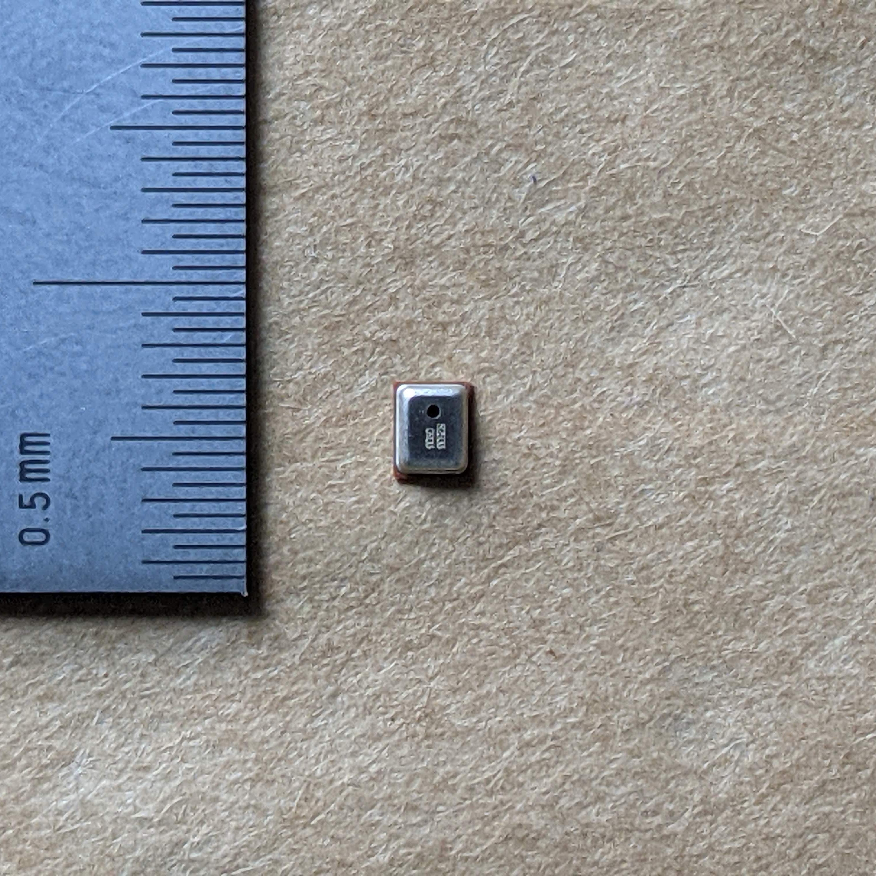
The microphone selection was rather difficult due to a lack of specificaitons available with amplified MEMS microphones. Knowles SPW2430HR5H-B was selected, as it seemed reasonable and could be tested with Adafruit's breakout board fairly easily.
Using a built-in amplified MEMS microphone decreases the number of component placements and simplifies layout and verificiton, at the expense of not having instrumentation knowledge of your audio response.
Button
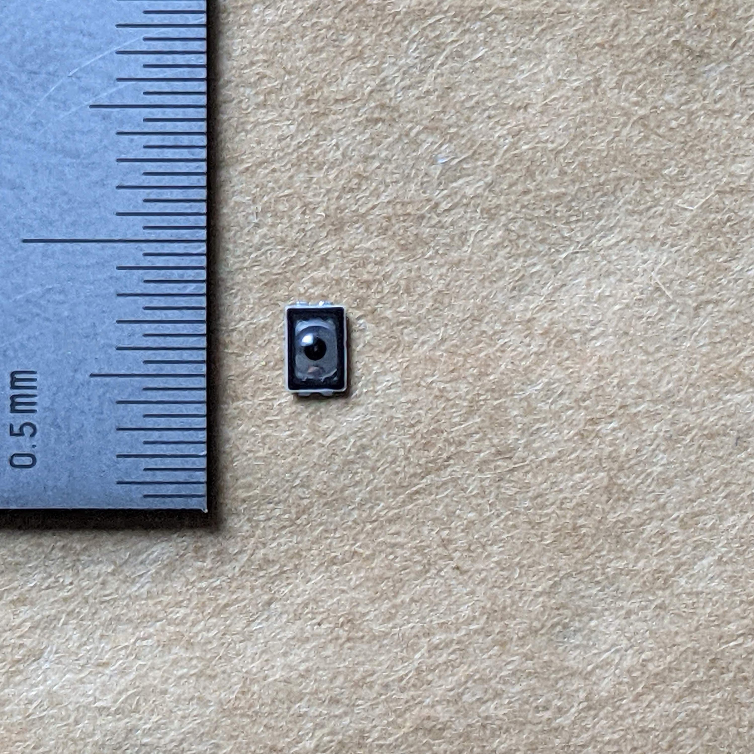
C&K KXT3 series provides ultra low profile miniature tactile switches and we chose KXT311LHS, with a low actuation force of 100g. It can be easily pressed with the edge of your nail, or a bit less comfortably with the back.
The button provides the functionality of changing light patterns by pressing and triggering it into a low power sleep mode by holding for 500 ms. Completely available as an interupt to the microcontroller, so other uses can be implemented.
IMU
LSM6DSM is a 6DOF IMU with a three-axis accelerometer and three-axis gyroscope by STMicroelectronics. It communicates over I2C and is connected to the hardware I2C peripheral in the microcontroller. It allows a fast data stream at very low power. It also has additional low power modes and the ability to wake the main microcontroller over interupt with the routed interupt pin.
Passives
There are three passives (five if the IMU is populated) that can be of any tolerance. There are two 1 uF and 0.1 uF decoupling capacitors and one 10k pullup on the reset of the processor. The two IMU pullups are 10k I2C pullups.
Alignment Pins
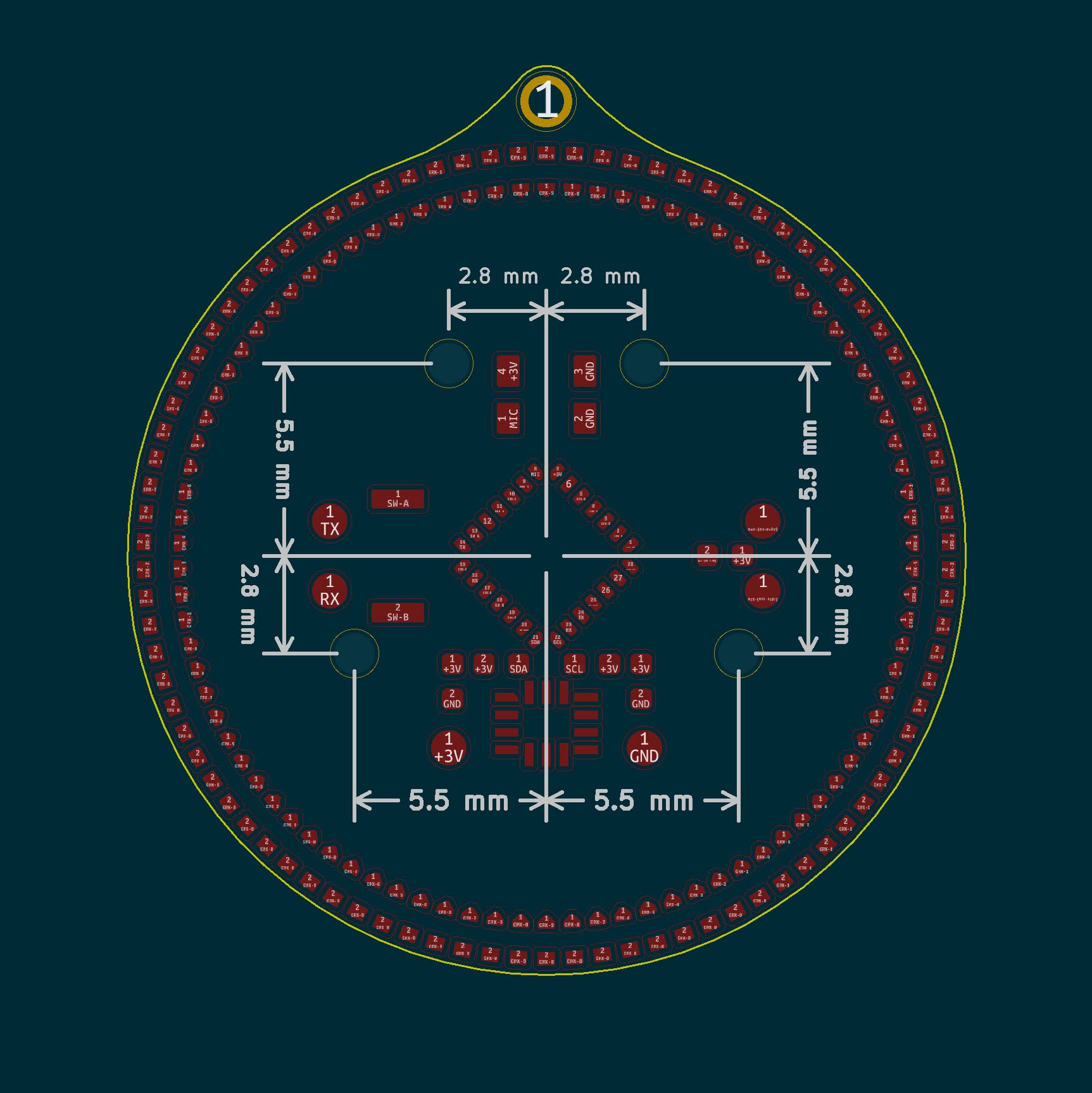
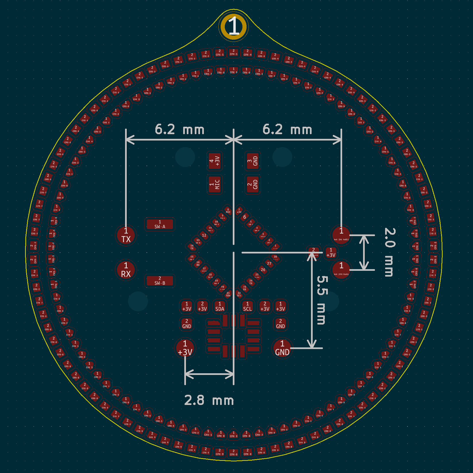
There are four tooling holes/alignment pins that can be used for addons. They are 1.152 mm (45.35 mil) in diameter and are placed 2.8 mm and 5.5 mm from the center.
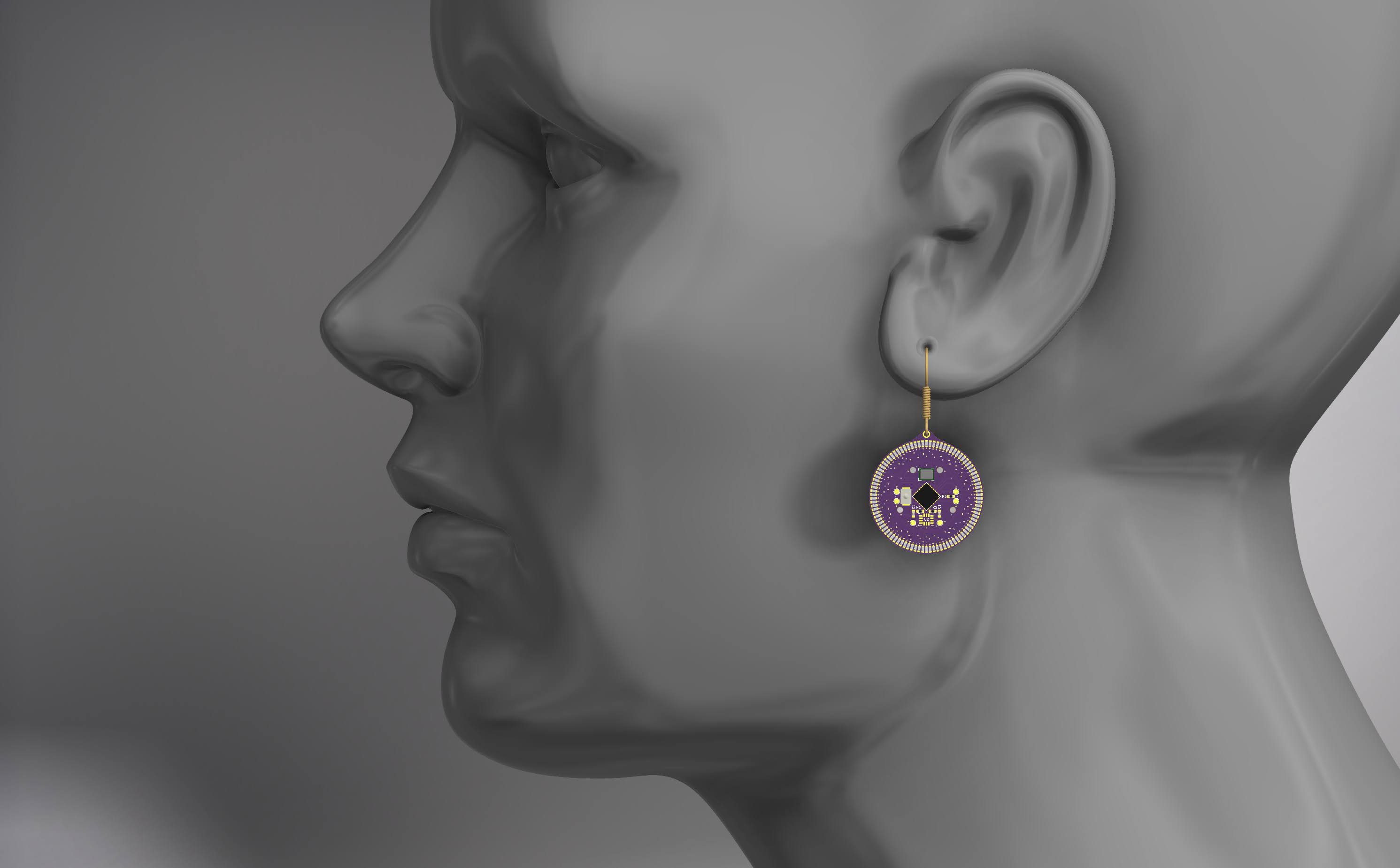
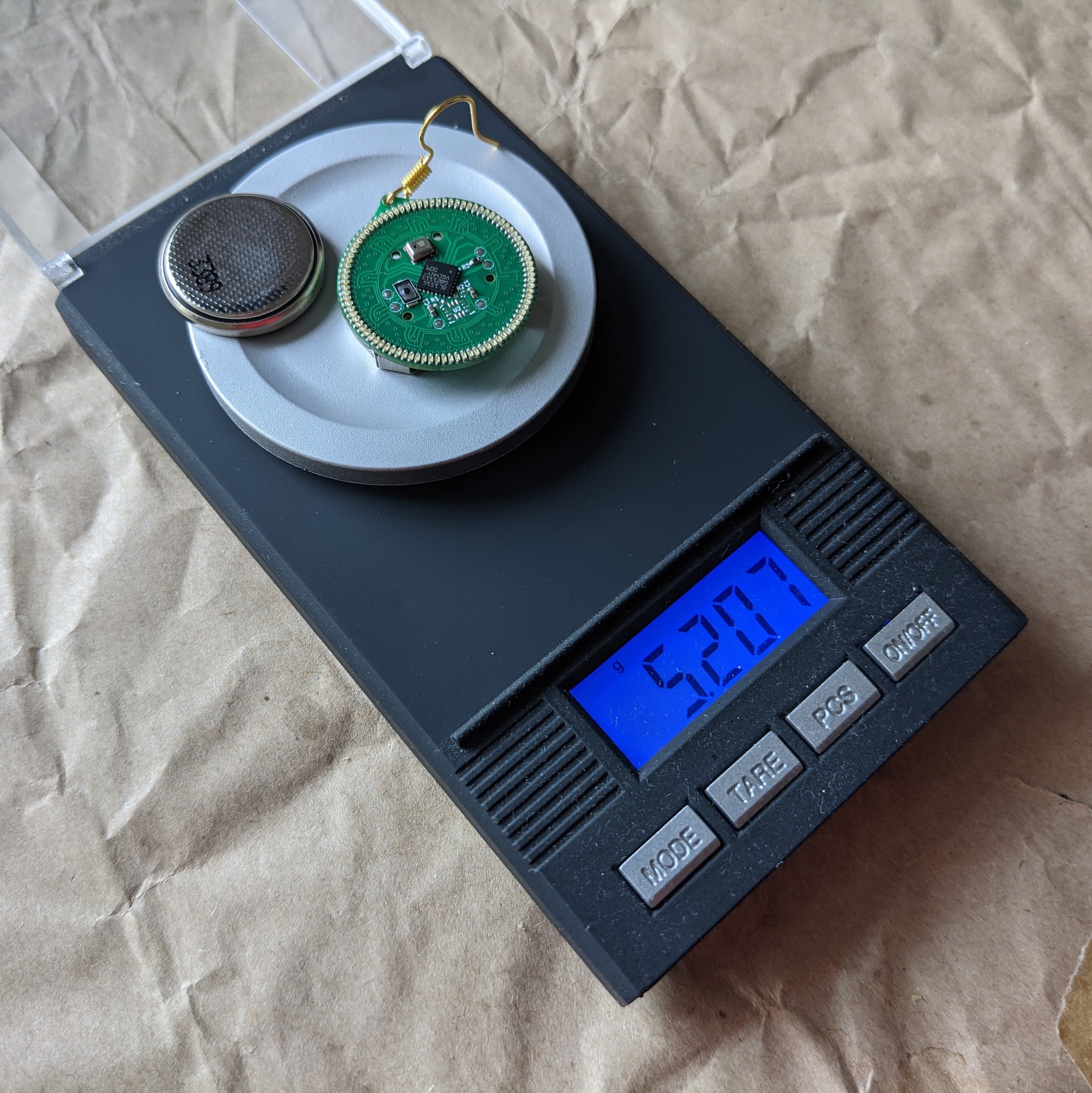
The earring is 24 mm in diameter, has a mass of 5.207 g (2.135 g without the battery) and the top eylet extends 2 mm extra, yeilding a bounding box of 24 mm x 26 mm x 6.36 mm.
Connectors
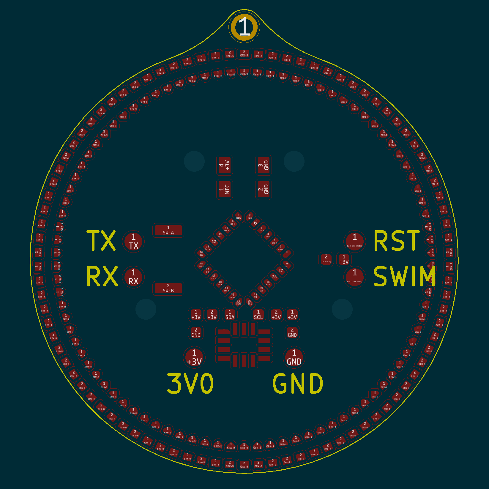
The only connectors on the board are six ⌀ 1 mm copper circles that are exposed as contacts for spring pins. They are placed evenly across the board so it receives balanced forces from the custom programmer (or testing jig).
| Labels | Dimentions |
|---|---|
 |
 |
The labeled pins have their descriptions in the table below.
| Pin | Description |
|---|---|
| 3V0 | Connected to Batt+ and power net |
| GND | Connectedto ground net |
| TX | GPIO PB2 for serial out |
| RX | GPIO PB4 for serial in |
| RST | Active low, 10k pullup |
| SWIM | Programing interface |
Case
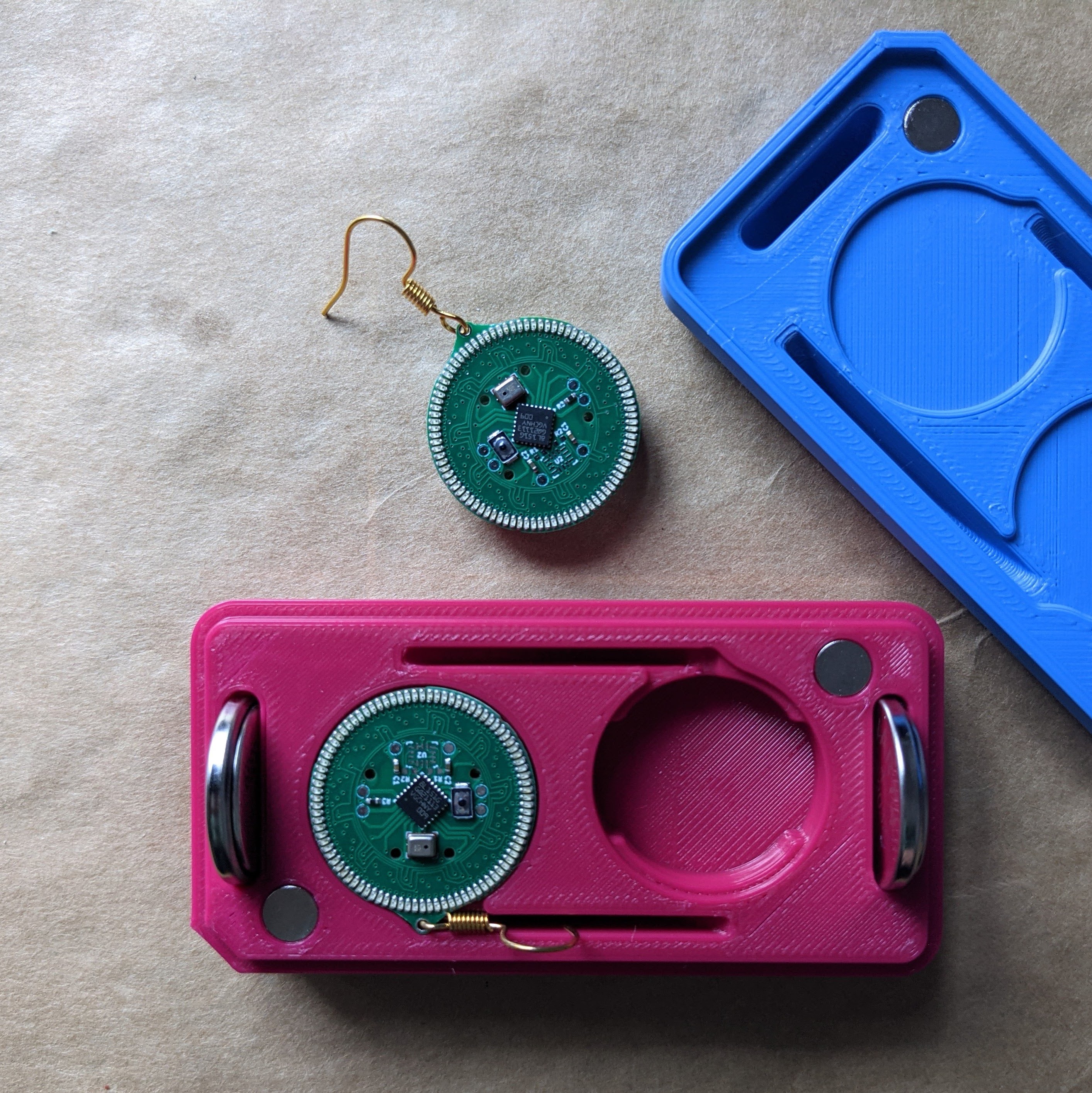
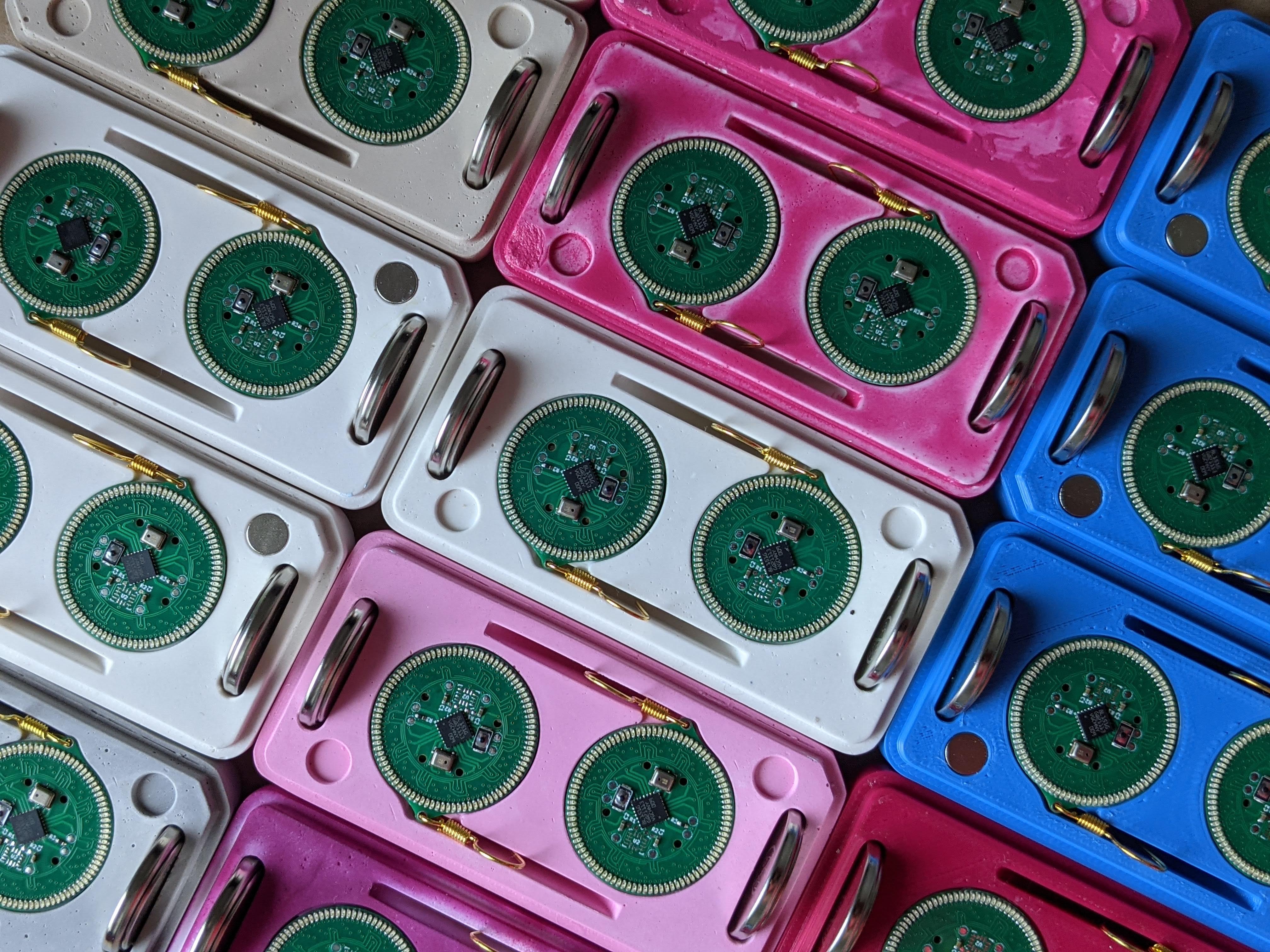
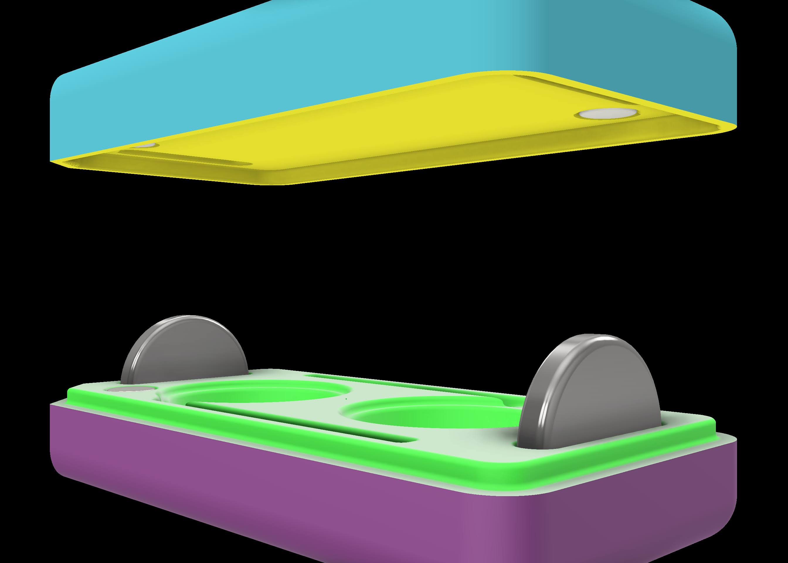
The case holds the earrings and two cells in its cavities. This allows for the storing and organizing of at least 36 hours of available runtime. The earring case consists of two pieces held together with magnets. The cavities inside the case hold all components securely so that they do not rattle. The earrings are displayed beautifully when the case is opened.
The case is designed in CAD and made to house two earrings (with or without batteries inserted) as well as two additional batteries. All of the edges are filleted and the closed case is comfortable when held. One corner is chamfered which makes it easier to align both pieces together in the correct orientation, and the magnets are oriented to resist trying to close it whenever the directionality does not match. It also provides a very satisfying tactile click when they align and close.
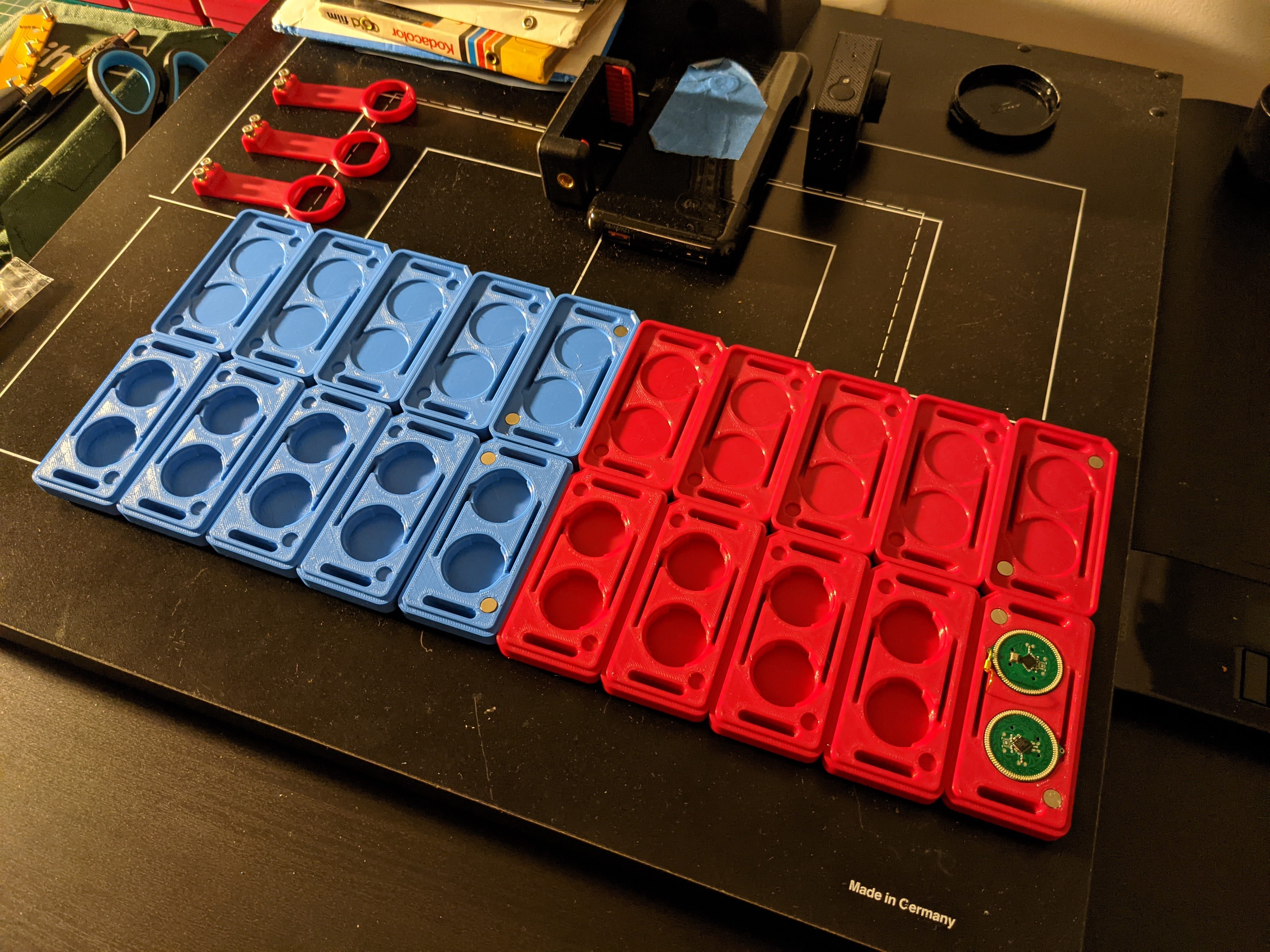
FDM Printed
The first sets of cases are made of 3D printed plastic PLA. The top and bottom have bold contrasting colors that uniquely identify the brand. They are printed with a 20% gyroid infill and at 200 um layer height. The 3D models must be scaled up to 100.2% to account for PLA shrinkage.
Cast
For a more bold and distinctive style with a pebble or smooth seashell-like finish, casted cases provides an air of luxury using distinctive materials.
Mould Master
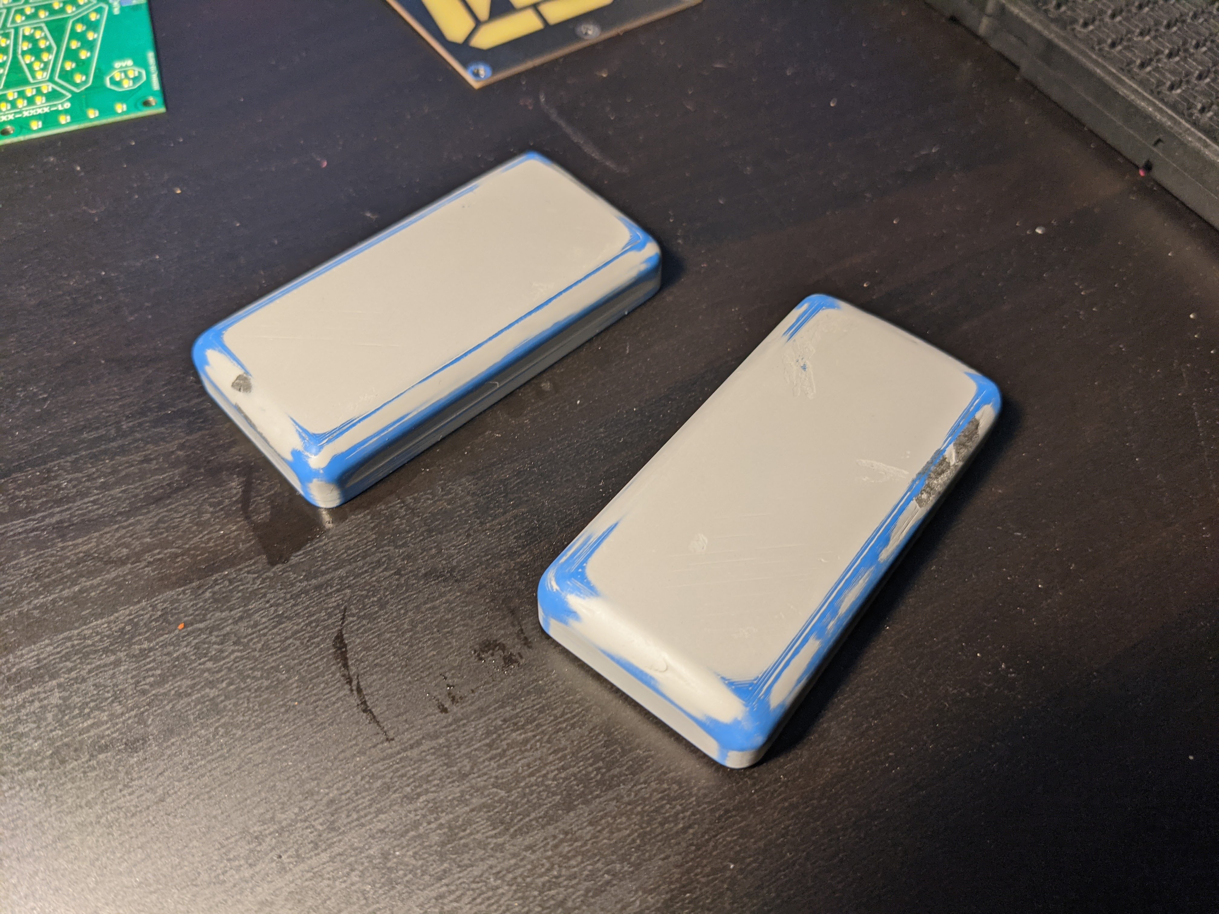
Moulding masters were made using the same 3D printed designs, printed at an 80 um layer height, and then repeatedly filled, primed, and sanded with P400 to P3000 grit sandpaper on top of a glass plate to keep the straight faces square. This fills all of the air gaps and allows for a very smooth finish. It is then buffed to a shine with nail buffer sponges.
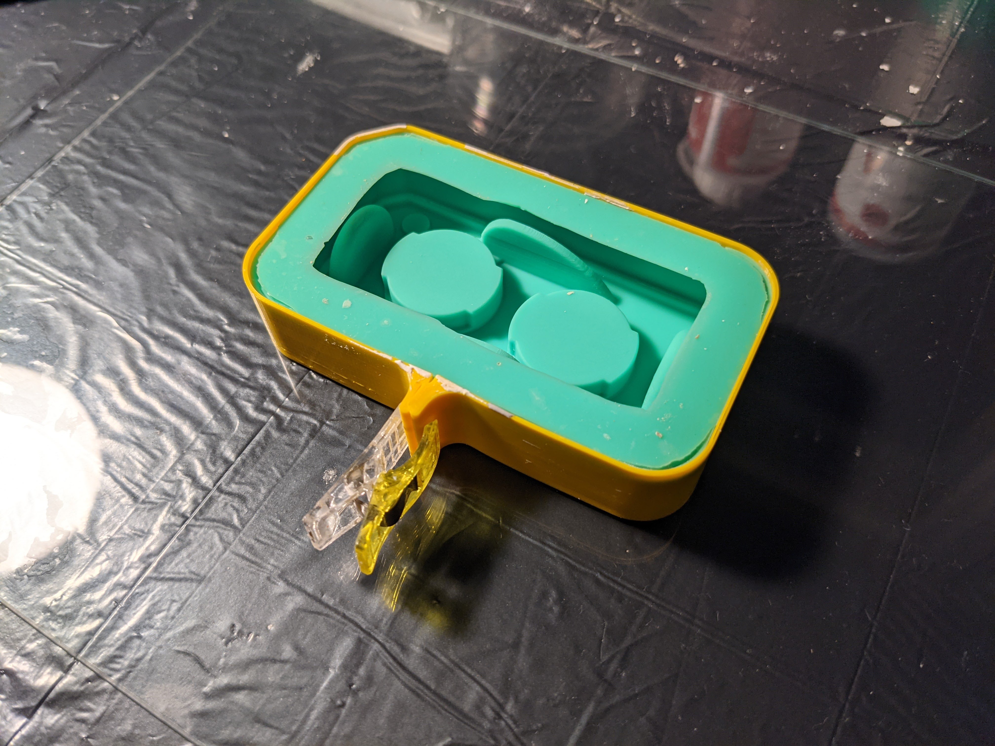
Silicone Mould
A platinum cure shore A20 silicone rubber (Troll Factory TYP-1) is used to make a mould of the master. This has an accuracy of ~2 um so it's able to reproduce a surface finish. Since the back is flat, an open-faced mould is made. The part, as well as the walls, are held in place with Quakehold museum wax, and mixing the exact amount of silicone needed (based on a CAD model) means a high yield. After curing, the mould box walls are cut off and the master is demoulded, yielding a silicone mould.
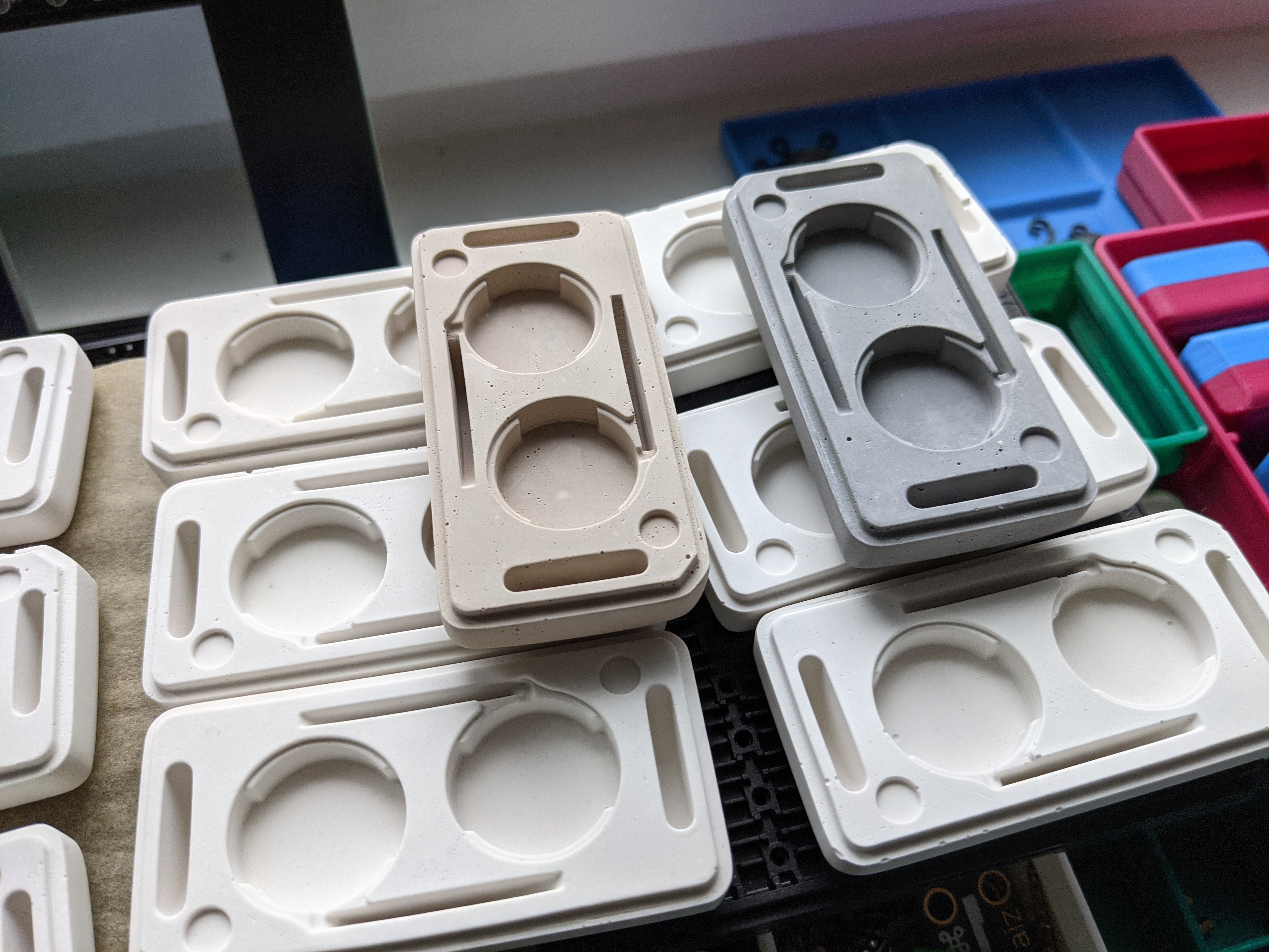
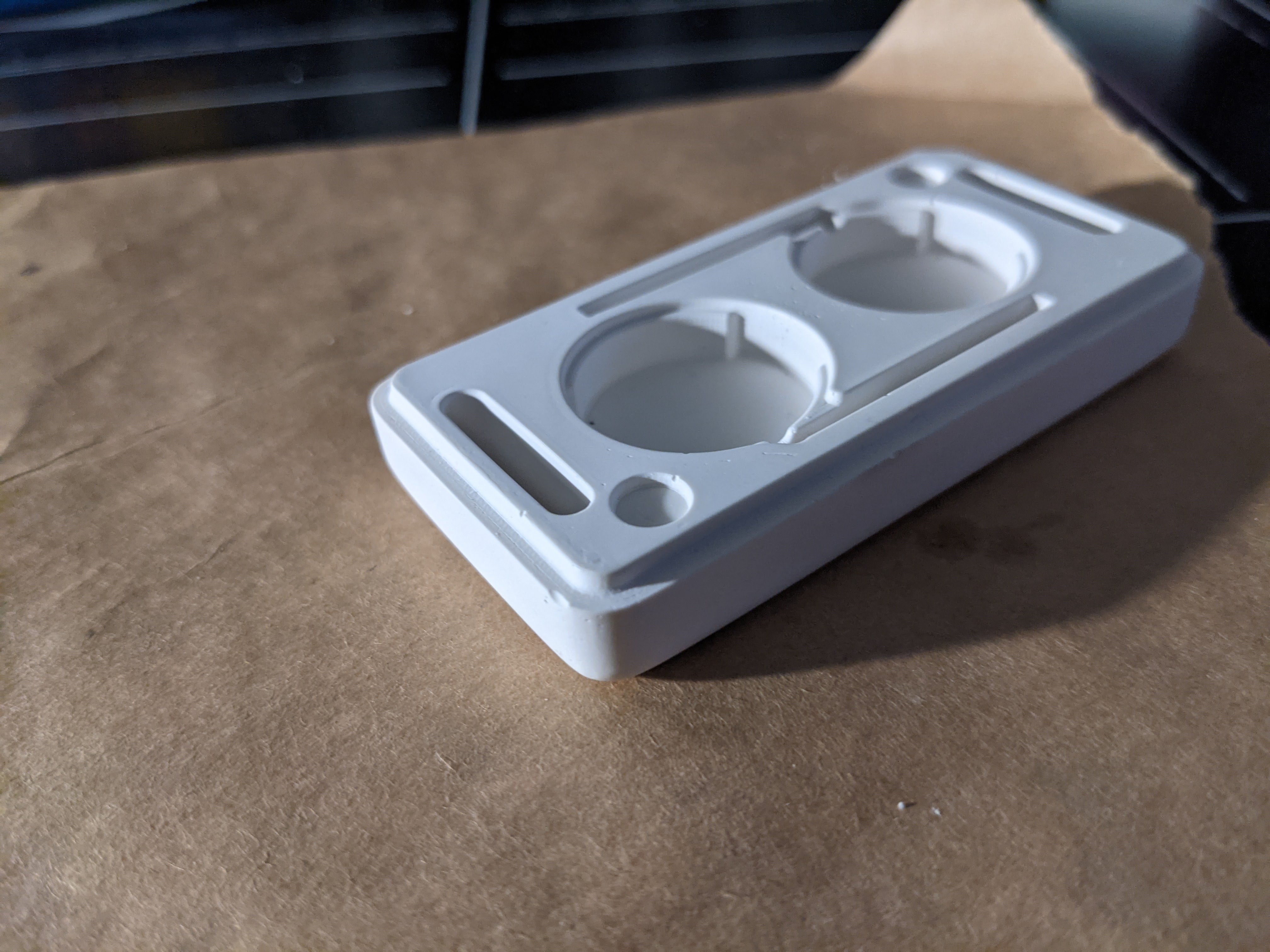
Stone Casting
The mould can be cast with various materials, including other silicones, polyuretane, rubbers, and resins. In our case, we used plaster. We are using high compressive strength Ernst Hinrichs Sockelgips FL Type-4 low expansion dental plaster. These plasters have a thixotropic agent that allows them to flow better, which means that they mix thinner and reproduce in finer detail. Applying a surfactant to the mould, mixing with distilled water, and using a vibrating table produces castings with fewer bubbles. The back is roughly leveled off and set to cure. The part is demoulded and the back is hand finished with P320-P3000 grit sandpaper.
After 24 hours, the part has cured to its final hardness and has dried out completely. It can then be processed further with magnets and dye.
Magnets
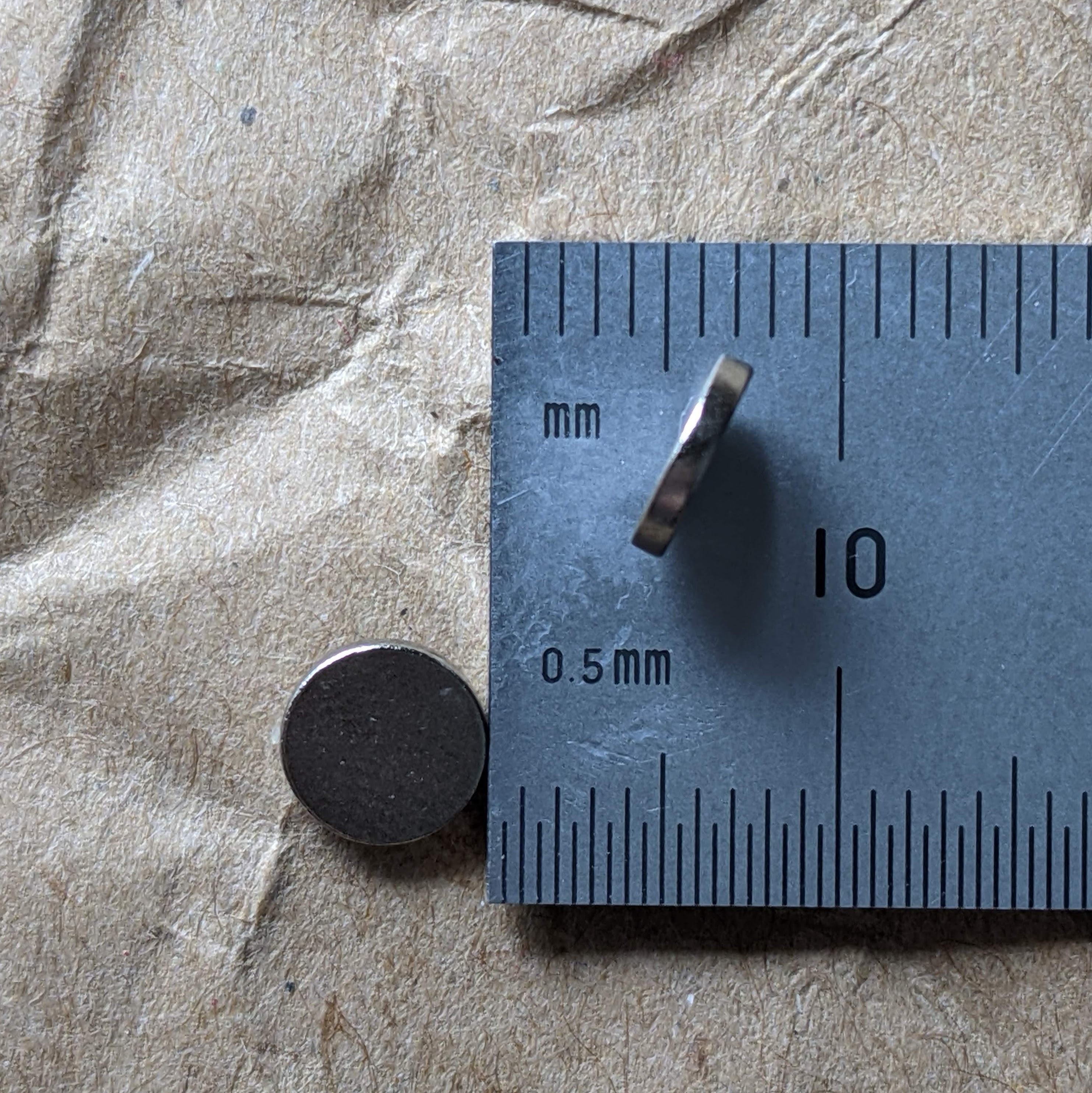
The magnets are 6 mm x 1 mm N52 neodynium magnets that are glued in with UHU Max Repair Extreme adhesive. They are coated in Ni-Cu-Ni, at around 12 um. The magnets are a very tight fit in their countersinks and are glued in to fit securely. They have a fixed orientation between both parts made, so swapping tops or bottoms with other sets is possible. There are few adhesives that work well when bonding two materials together that are already difficult to glue.
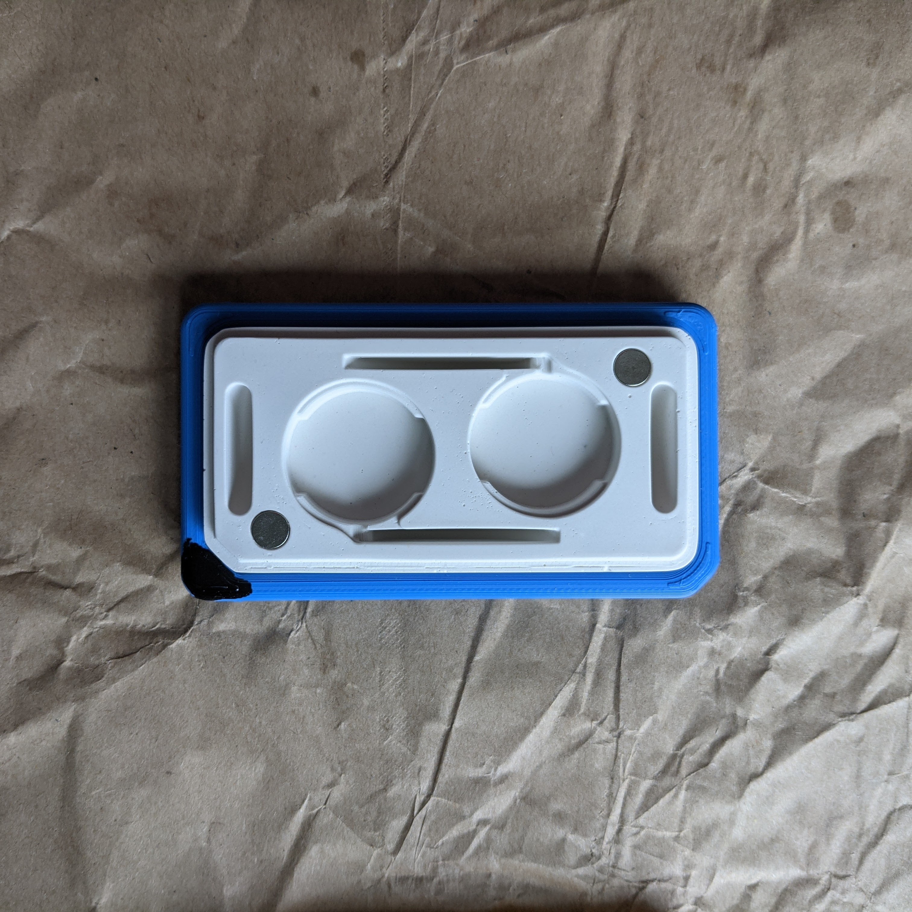
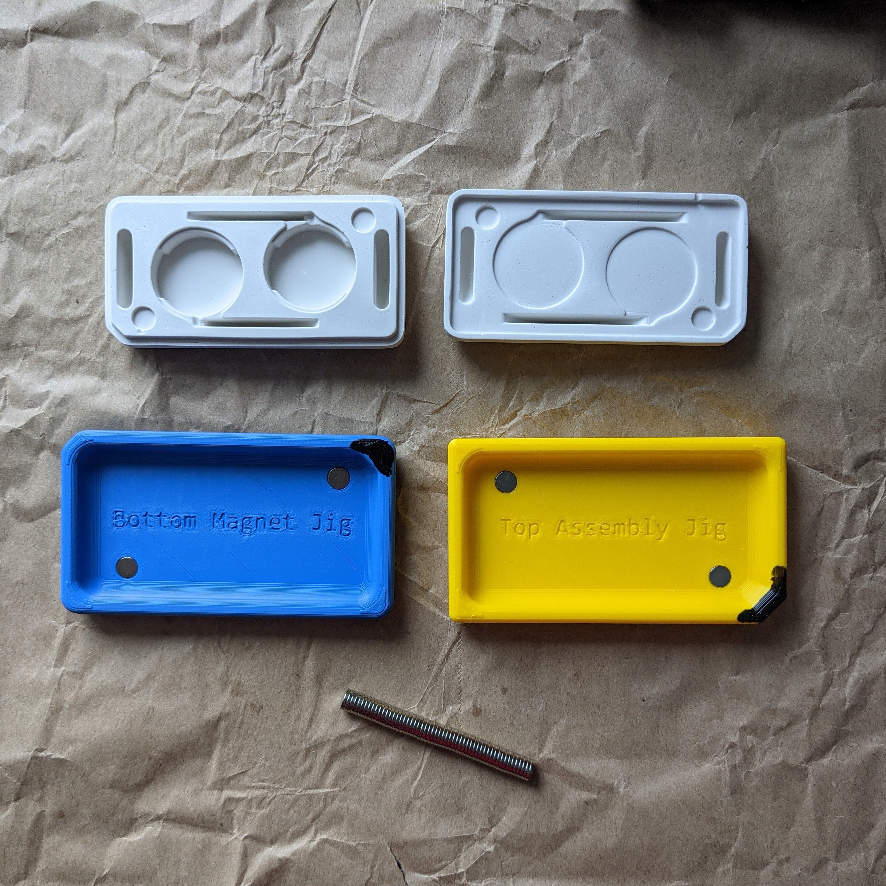
Magnets are installed using a gluing jig. One jig for the top and one for the bottom. Both jigs have magnets installed to correct for orientation when gluing. The jigs also have a matching chamfer which prevents the wrong part from being placed or placing the part backwards by accident.
The two jigs are color-coded as well. Adhesive is dispensed into the wells and the magnet is dropped, which automatically orients itself with the jig magnet. It can then be removed and set to cure.
Firmware
The firmware is coded at the register level in C. The code is fully interupt-based and performs quite efficently. The toolchain is simple and built on open source tools. This makes it harder to code, but allows for significant optimization.
Modes
There are multiple modes available on the halo earring that can be switched through when pressing the button. Each press of the button cycles to the next mode, eventually circling back around.
| Audio | Halo | Sparkle |
|---|---|---|
 |
 |
 |
Dynamic
The mode selected on startup is the audio-based dynamic mode. During every ADC cycle it reads the analog value and projects the audio waveform amplitude, based around a moving point on the ring with wrap around.
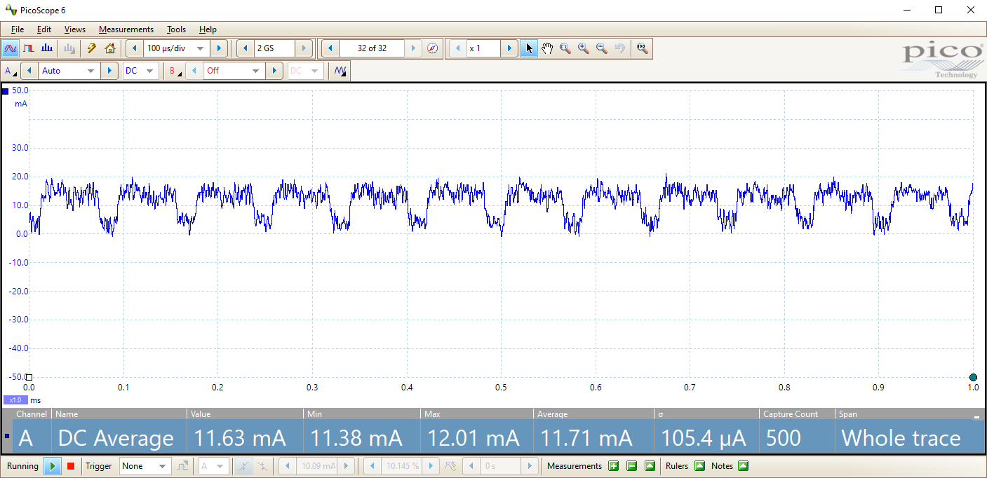
Power profile readings show no correlation with audio level, and an 11.71 mA power consumption with 105 uA standard deviation. Projected battery life with a 220 mA CR2032 cell is ~18.8 hours.
Halo
In the HALO mode, the entire light ring is lit. This is done through interlacing the illumination of each LED. The deep sleep auto wakeup timer is set to wake up every two clock cycles of the low speed 32 kHz oscillator. On every wake, it changes to illuminate the 13th following LED, wrapping around at 90.
setLed((prevLed + 13)%90);This allows for a cleaner and more consistent scan over the entire halo ring since 13 is the greatest integer factor (besides 91), for all of the LEDs to be turned on evenly around the ring. Greater spacing causes frames to interlace with one another, resulting in a cleaner visual experience.
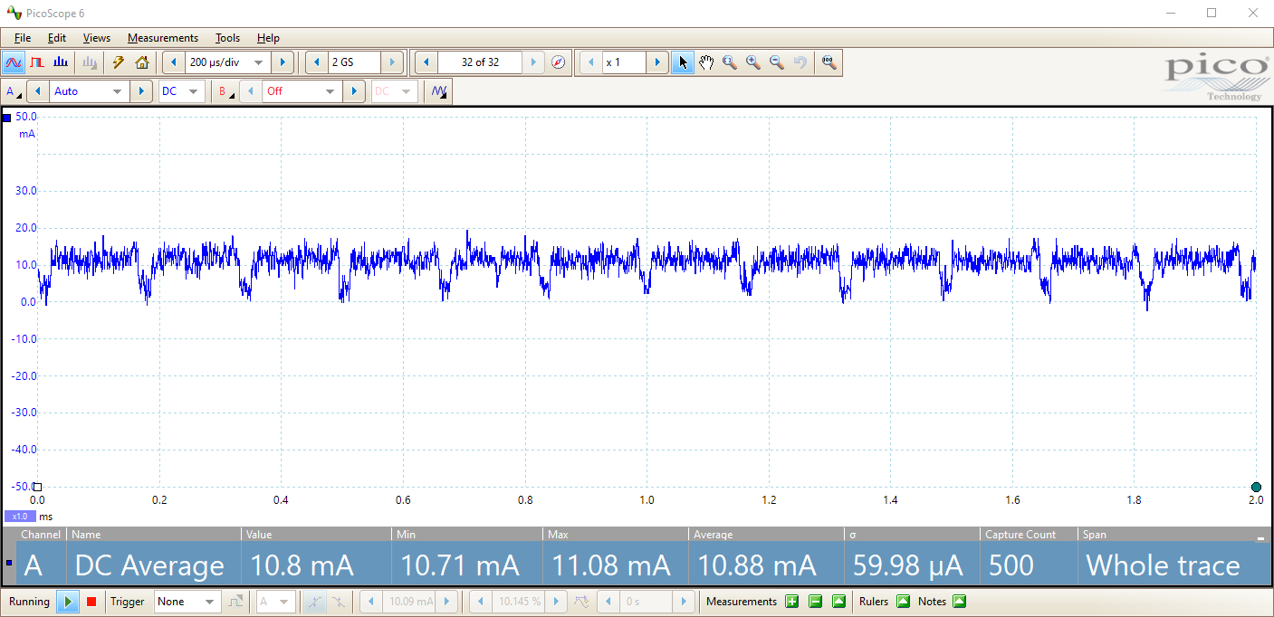
Power profile readings show a 10.88 mA power consumption with 60 uA standard deviation. Projected battery life with a 220 mA CR2032 cell is ~20.2 hours.
Sparkle
Sparkle mode is the best for minimal power draw and is implemented in a single line of code. At ~320 Hz, the procesor wakes from deep sleep and runs the selection of which LED to light (if any).
rand()%15 ? ledLow(prevLed) : setLed(rand() % 90);Given a 1/15 chance, a random LED will light up. Othwerwise, any previously lit LEDs will be turned off. This results in a more visually pleasing pattern over just randomly lighting LEDs, which produce sharper bursts of light. Since the processor is only awake 0.002% of the time, and the LED has a chance of being on only 6.6% of the time, the power consumption is quite minimial.
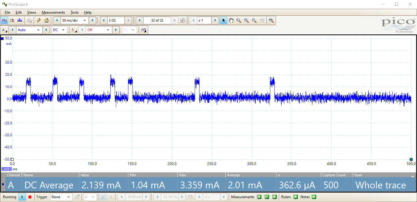
Power profile readings show a 2.01 mA power consumption with 327 uA standard deviation. Projected battery life with a 220 mA CR2032 cell is ~109.5 hours, (over 4.5 days).
Power Managment
Pressing and holding the button for 500 ms will turn off all LEDs and put the cpu into deep sleep mode. In this mode the current draw is around 15 uA and the only wake interupt is the button press.
Pressing and holding the button will show a boot-up animation that lights up in a ring around the face. Holding the button until it makes a full revolution, about one second, will trigger a software reset of the halo, turning it back on.
LED control
Since the LEDs are configured in a charlieplex array, only one LED can be on at a time. Some optimization can allow multiple LEDs to light simultaneously, but at a cost of consistency in brightness and power draw. There are two low-level functions that can turn a individual LED on or off, as well as a helper function that remembers the last LED and turns it off before turning on the next one.
void setLed(uint8_t led);
void ledHigh(uint8_t led);
void ledLow(uint8_t led);
The function to get the column and row from the LED number is shown below:
uint8_t col = led / 9;
uint8_t topElements = 9 - col;
uint8_t row = 9 - (led % 9);
if (topElements <= (9 - row)) {
  row--;
}
To turn the LEDs off, the column and row are both set to high impedence. To turn it on, the column is set high and the row is set low.
The previous LED must be turned off before lighting up the next LED or else there is a risk of damaging the electronics. It is recommended to only use the setLed and ledLow functions.
Compiling
Compiling is done with the SDCC ("Small Device C Compiler") and the included makefile.
As an example, the following steps are given for some systems but should easily be transferable to the distro of your choosing. The requirements are make and sdcc. They should both be available in the path. Once installation is completed, running make will generate the halo.ihx file, which is the binary to be flashed.
makeUbuntu/WSL
sudo apt install -y make
sudo apt install -y sdcc
Arch
sudo pacman -S make
sudo pacman -S sdcc
Flashing
Some form of flashing software is required, along with a programmer that can program over the SWIM protocol. We are using third party STLink-V2 clones, because the form factor of the genuine programmer is difficult to use and newer programmers do not support SWIM.
Windows
STVP_CmdLine is required as the flashing software and comes with the software package ST Visual Programer. This needs to be installed and c/Program Files (x86)/STMicroelectronics/st_toolset/stvp/STVP_CmdLine.exe needs to be added into the path.
Once it's installed, it can be run with the following flags. Preferably in WSL but should also be possible in CMD or PS.
STVP_CmdLine.exe -Device=STM8L15xG4 -FileProg=halo.ihx -verif -no_loop -no_logIt is also incorporated into the make file and can be run with the following:
make flashLinux
[STM8 Flash] is an open source SWIM compatible flashing utililty for linux. The tool is built from source. Short instructions are written below.
git clone https://github.com/vdudouyt/stm8flash.git
cd stm8flash
make
sudo make install
Flashing can then be done with the following command:
stm8flash -cstlink -pstm8l151 -w halo.ihxIt is also incorporated into the make file and can be run with the following:
make flashAbsolute Maximum Ratings
| Parameter | Min | Max | Unit |
|---|---|---|---|
| Battery Voltage | -0.3 | 3.6 | Volt |
| Temperature | -40 | 85 | °C |
| Power Draw | 15u | 25m | Amp |
Guaranteed Ratings
| Parameter | Min | Max | Unit |
|---|---|---|---|
| Battery Voltage | 1.8 | 3.6 | Volt |
| Operating Temperature | -20 | 50 | °C |
| Storage Temperature | -40 | 85 | °C |
The earrings should be fine to leave in a hot car (although the 3D printed plastic case could warp). If you are outside of these ratings, take care of yourself, you are either freezing or at risk of heat stroke. The earrings will be fine.
Manufacturing
Although taking on novel uses of materials, the ability to manufacture at scale was always a primary focus. Parts were selected with strong supply chains and alternatives. Layout was designed with generous rules to accomodate for as many fabs as possible and the number of unique components was minimized. The microphone and battery holder are from single vendors but they have proven track records and well-known supply chains. Alternatives to be tested are still proposed.
BOM
The BOM was selected with parts that are common to the high-volume Chinese manufacturing market, have strong supply chains, and have many alternatives available in case a supplier stops manufacture or supply dips occur. The number of unique parts was kept to a minimum and the maximum amount of features can be implemented with "free" pins, like the programming SMD pads. The table of BOM is shown below.
| REF | QTY | Manufacturer | MPN | Description |
|---|---|---|---|---|
| D1-D90 | 90 | Brightled | BL-HUB37A-AV-TRB | LED: RED 627-637nm 50mcd@20mA 0402 |
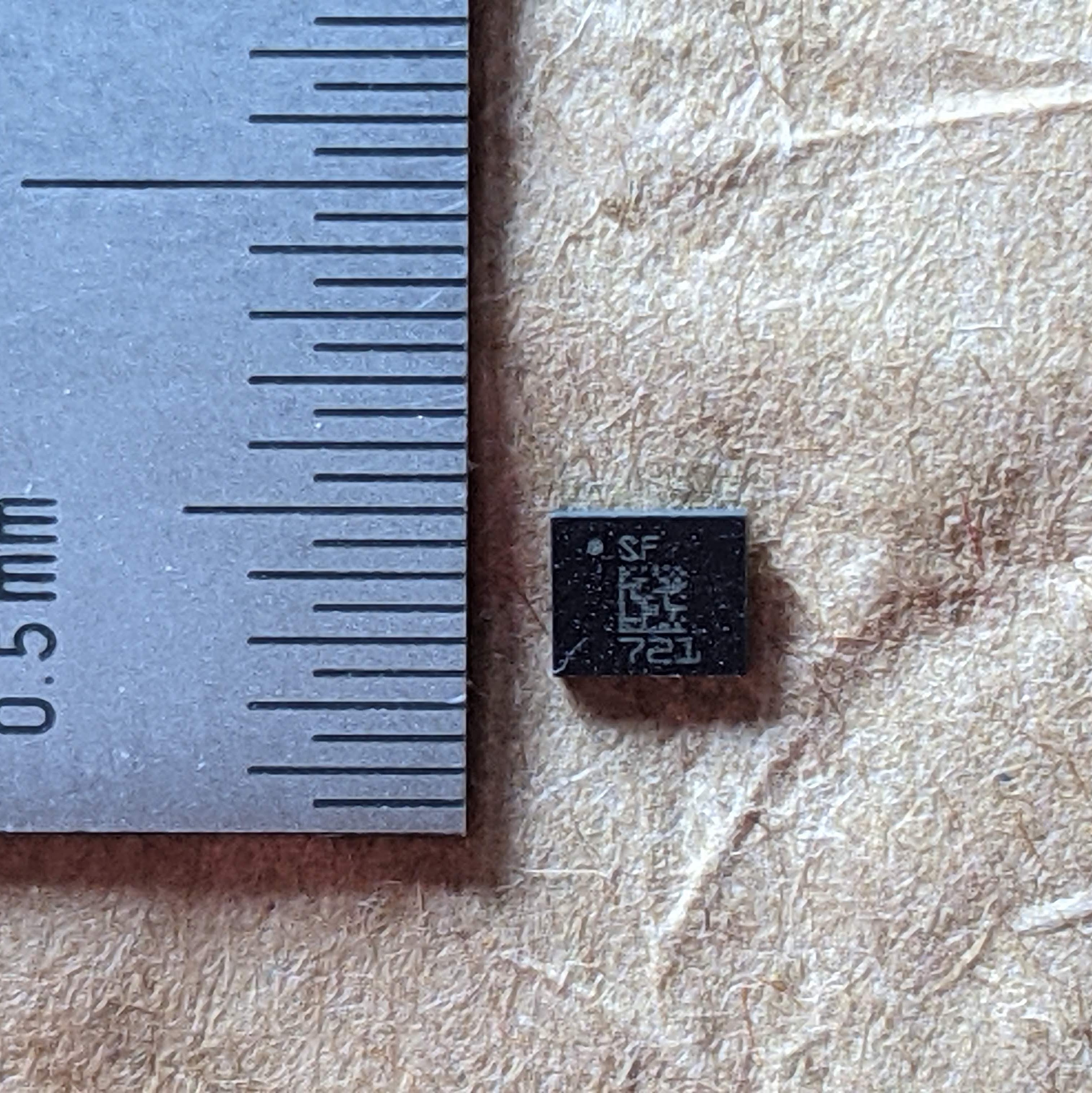
| U1 | 1 | STMicroelectronics | STM8L151G4U6 | MCU: 8b 16MHz 16k Flash UQFN-28-4x4 |
| MK1 | 1 | Knowles Electronics | SPW2430HR5H-B | MIC: Omni Si-Sonic 3.1x2.5x1.0mm |
| BT1 | 1 | Linx Technologies | BAT-HLD-001 | BAT: CR2032 Cell Holder |
| S1 | 1 | C&K | KXT311LHS | SW: Low Profile 3x2x0.6mm 100gf |
| R3 | 1 | Uniroyal | 0402WGF1002TCE | RES: 10k 5% 1/16W 0402 |
| C1 | 1 | Samsung Electro-Mechanics | CL05B104KO5NNNC | CAP: MLCC 100nF 16V 0402 |
| C2 | 1 | Samsung Electro-Mechanics | CL05A105KA5NQNC | CAP: MLCC 1uF 25V 0402 |
The csv is provided with the sources.
PCB
There is a single PCB. Although still common, some of the more precise requirements were needed to end up with a printed circuit board small enough.
| Paramter | Value | Unit |
|---|---|---|
| Height | 26 | mm |
| Width | 24 | mm |
| Layers | 4 | ul |
| Copper | 1.0 | oz |
| Copper Inner | 0.5 | oz |
| Thickness | 1.0 | mm |
| Material | FR4 | ul |
| Min Drill | 0.2 | mm |
| Trace Size | 5/5 | mil |
| Mask | Black | ul |
| Silk | White | ul |
| E-Test | Yes | ul |
| Surface Finish | ENIG | ul |
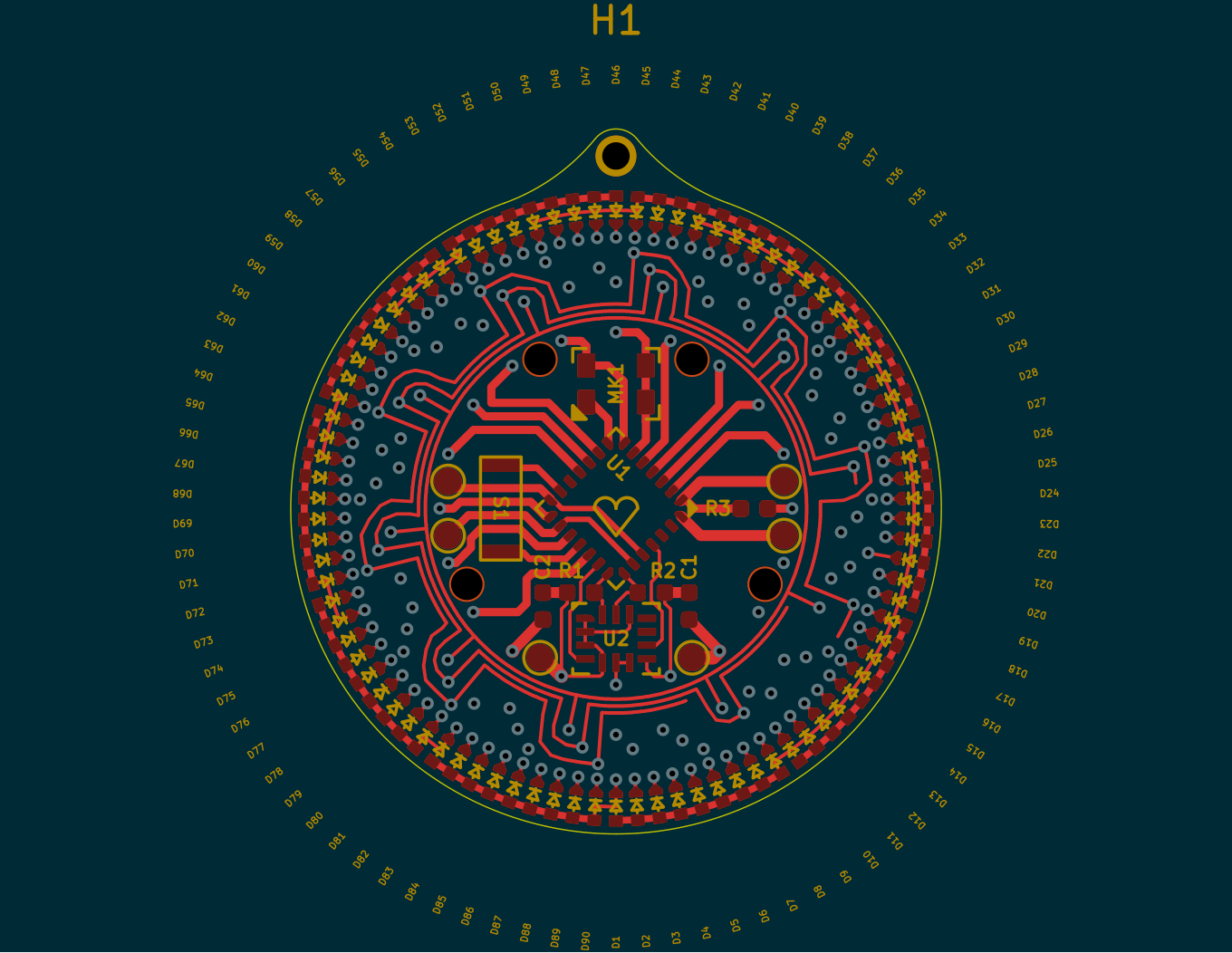
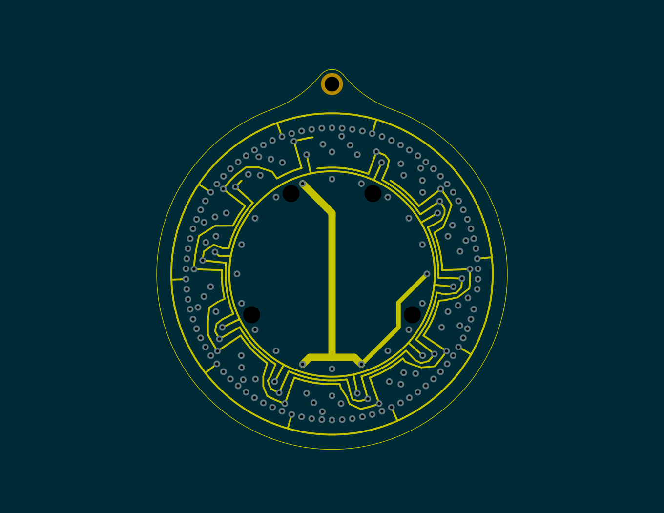
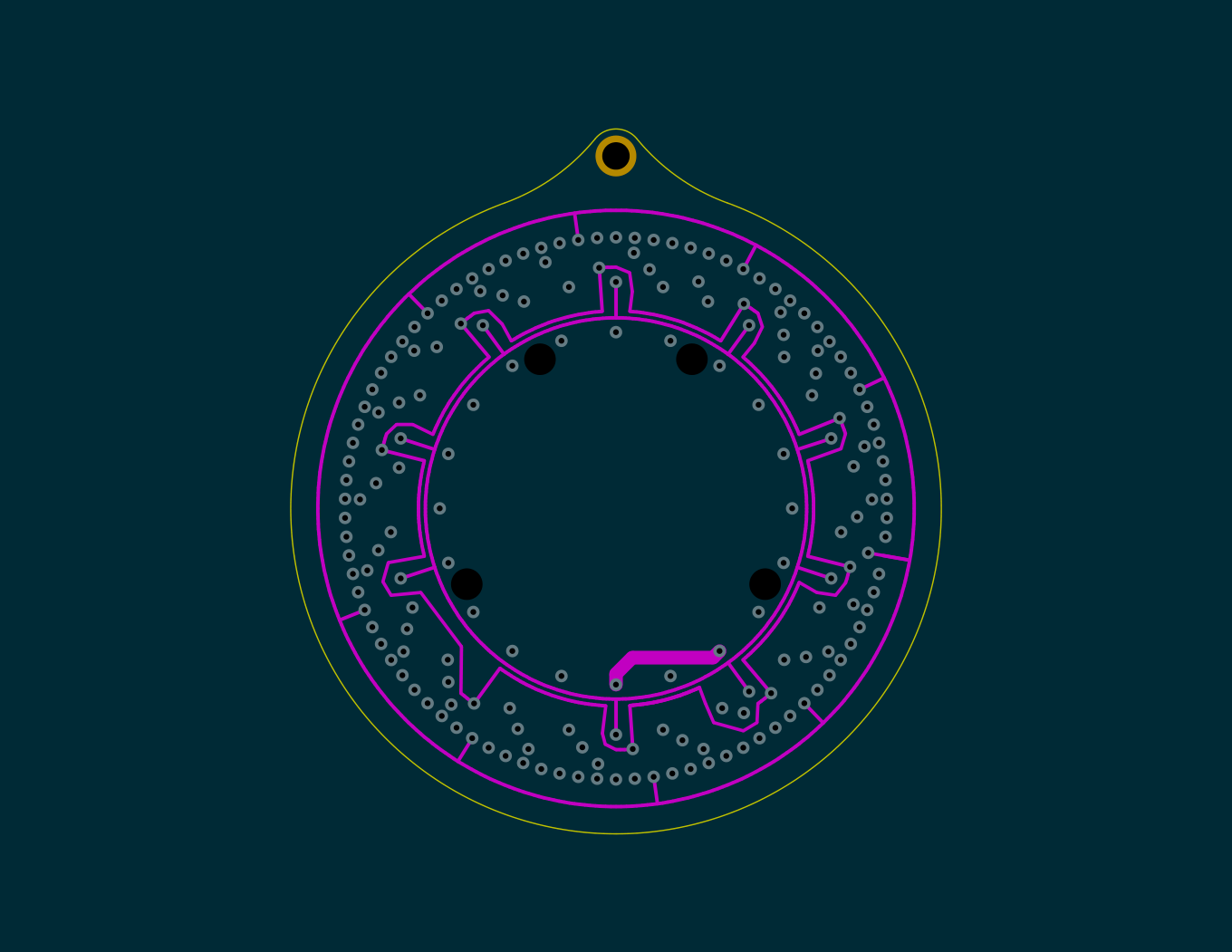
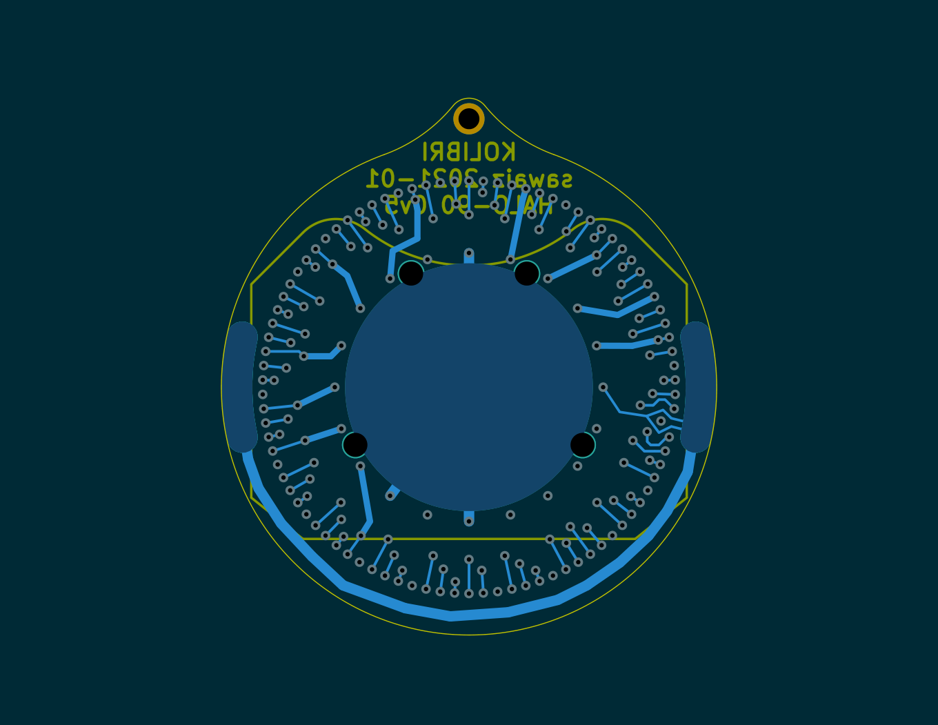
The PCB has four layers.
| Front | Inner 1 | Inner 2 | Back |
|---|---|---|---|
 |
 |
 |
 |
PCB Assembly
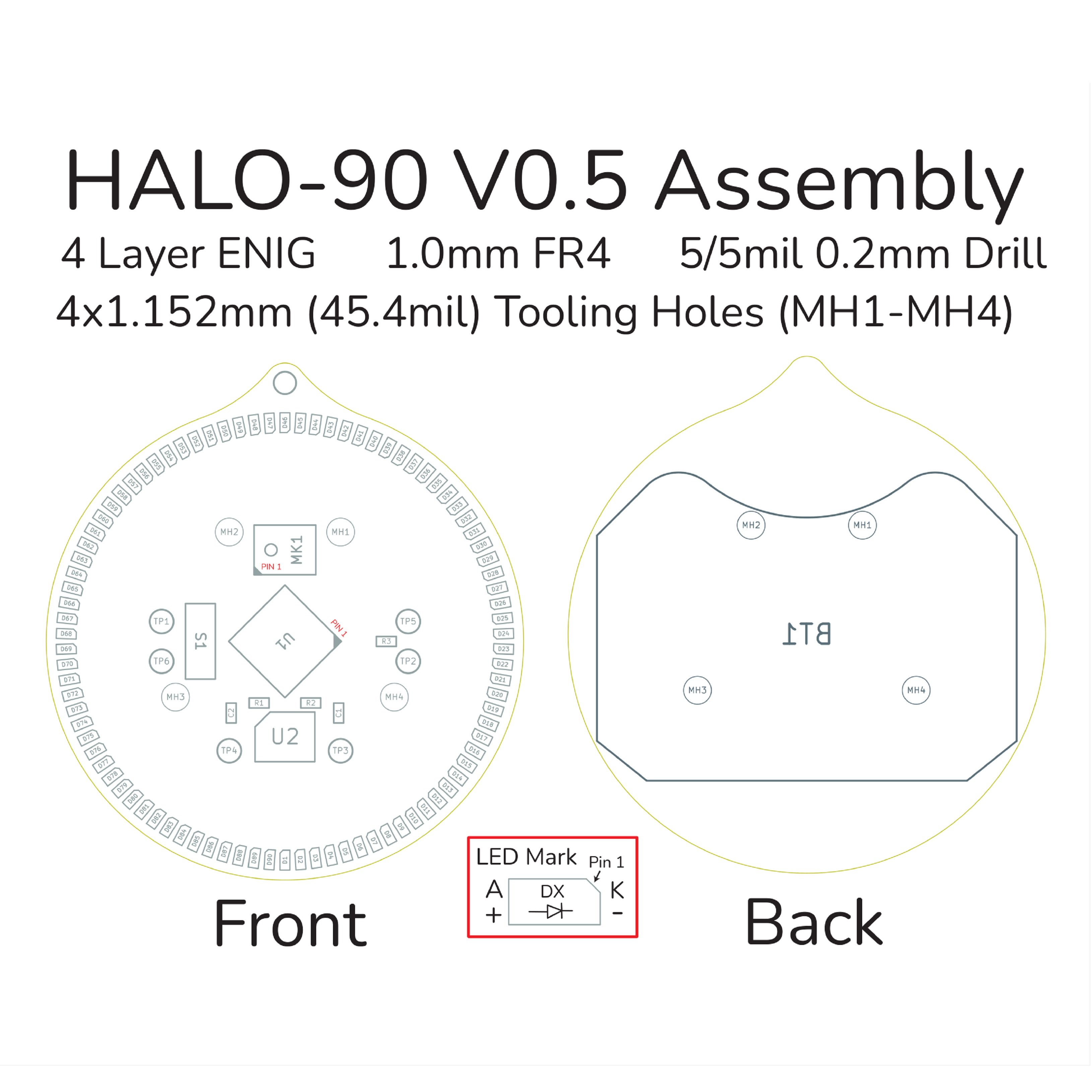
The whole board can be pick and placed. The table below shows some data that might be needed when requesting a quote.
| Parameter | Value |
|---|---|
| Uniqe Parts | 8 |
| SMD Parts | 8 |
| Placements | 97 |
| Solder Joints | 222 |
| Front Components | 96 |
| Back Components | 1 |
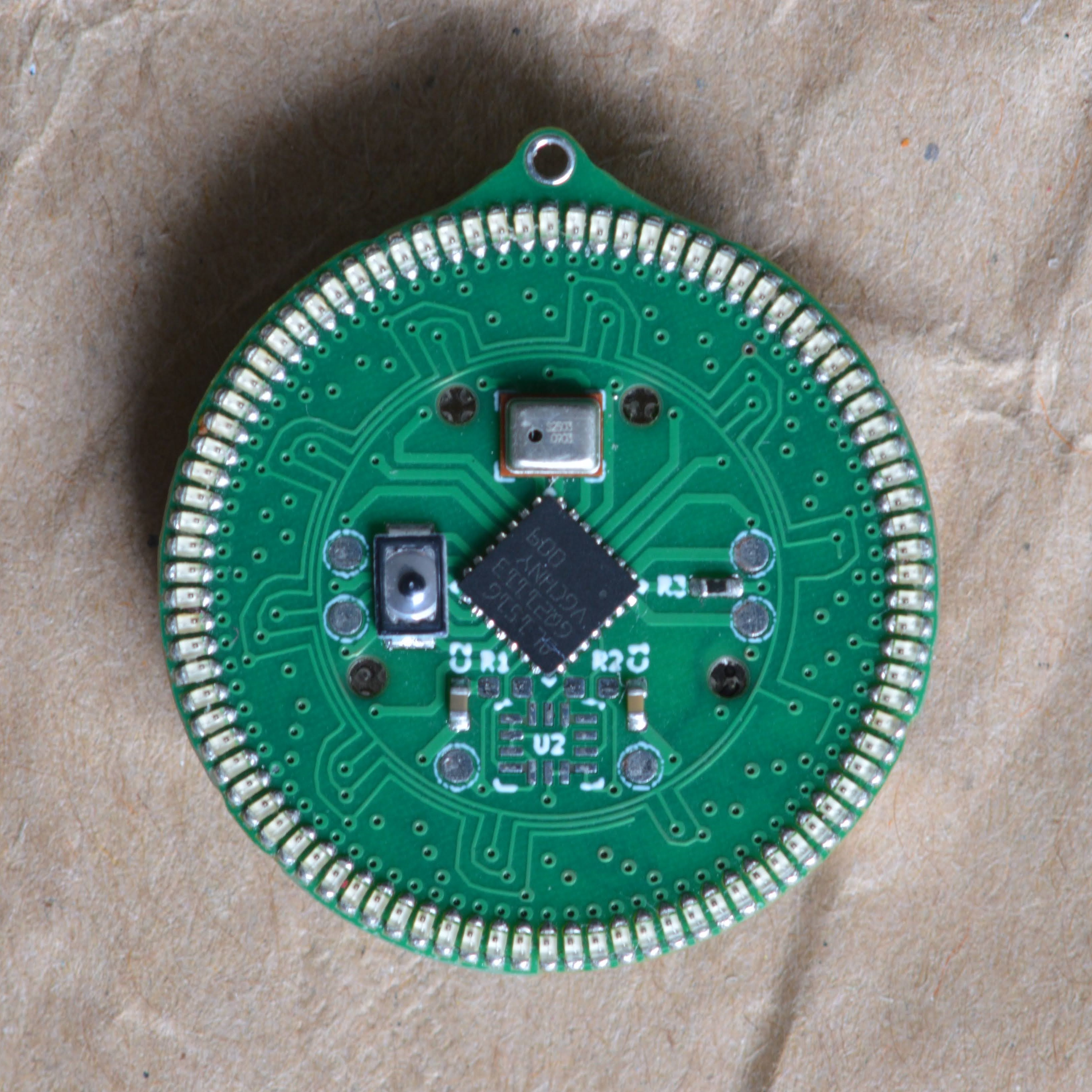
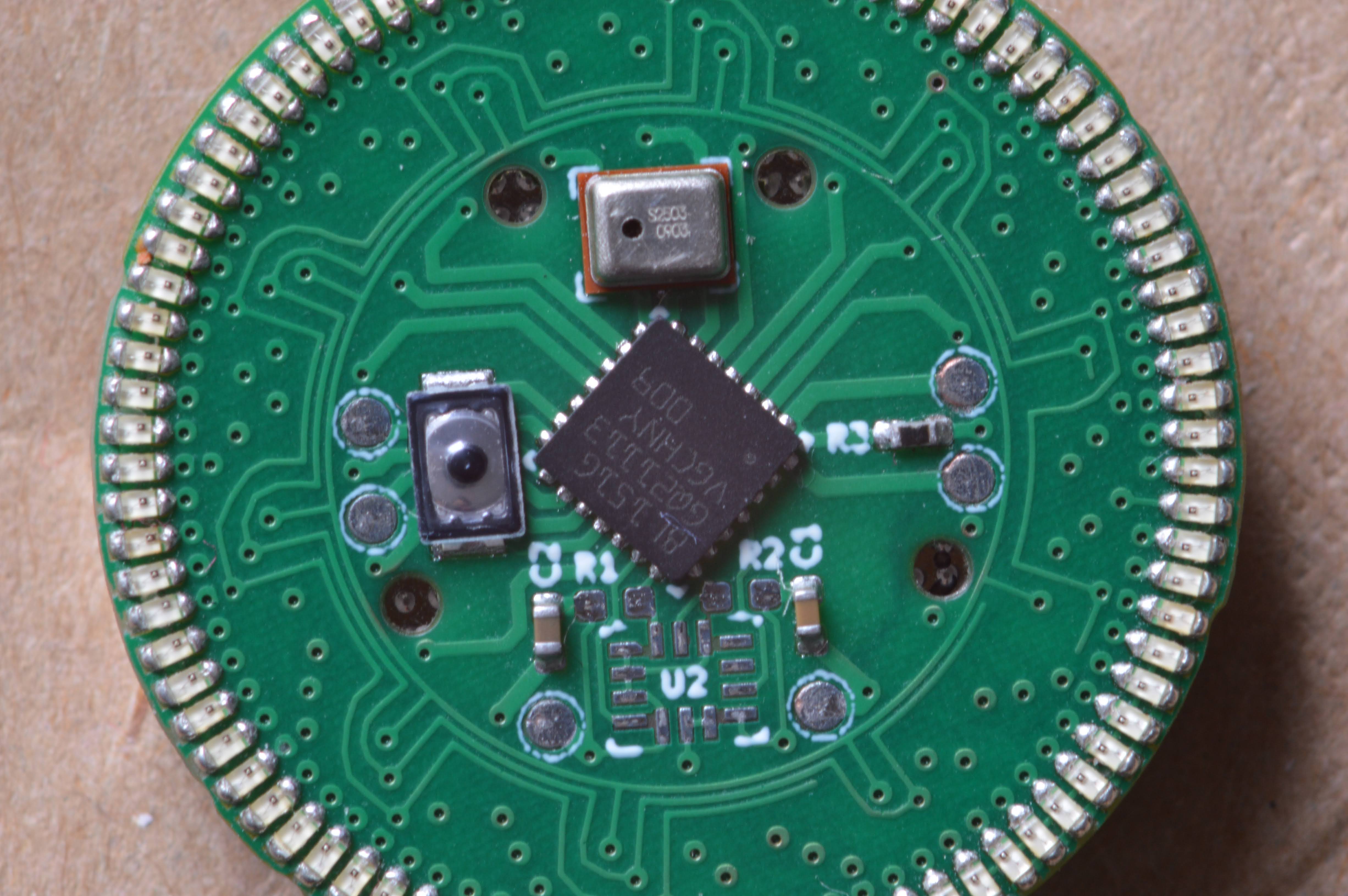
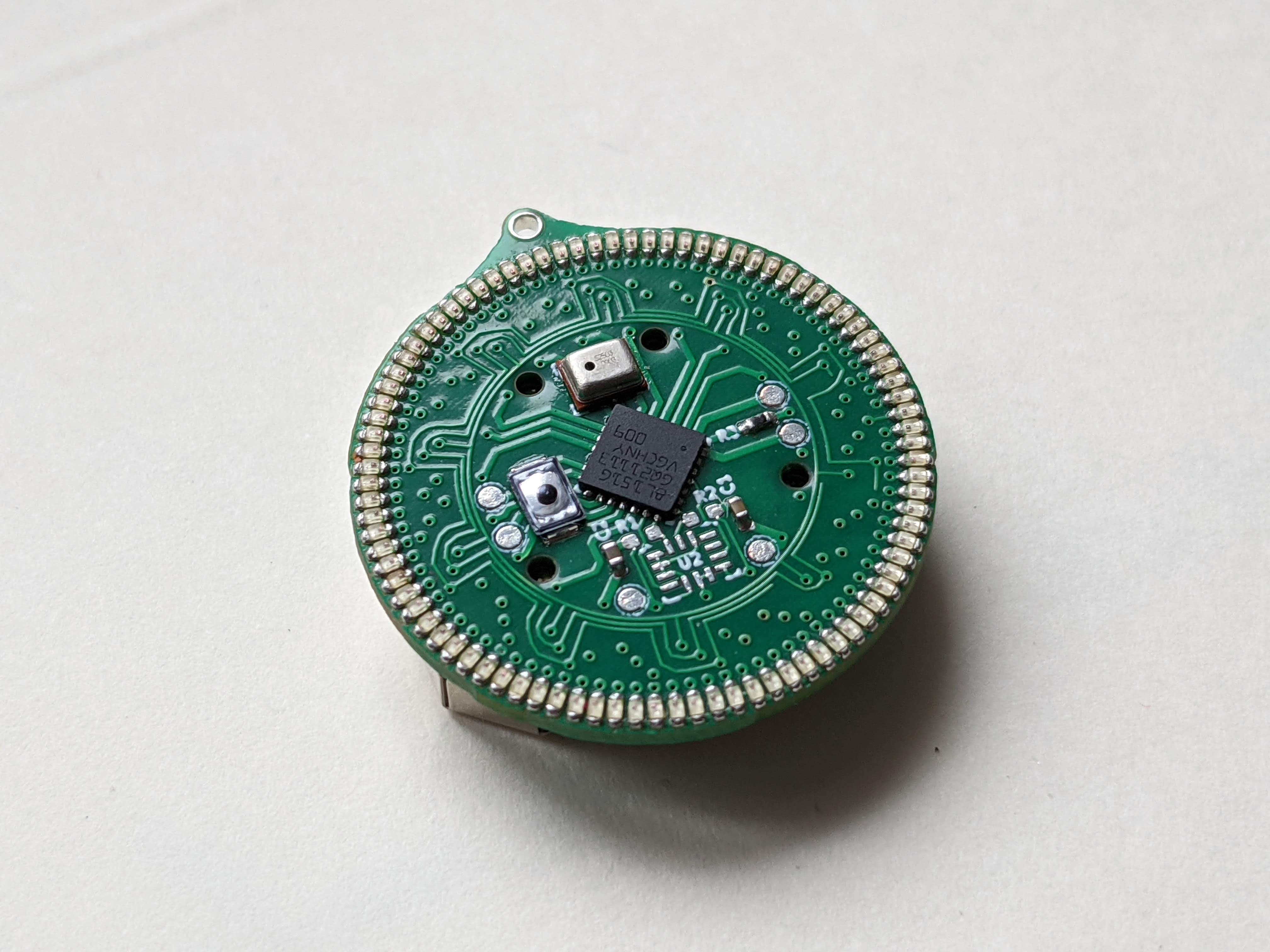
The smallest componts are 0402 LEDs, and all parts can survive normal lead-free reflow profiles. The microphone is open port MEMS so do not wash, clean, or expose it to ultrasonic vibrations (datasheet has further requirements).
Assembly Detail Pictures
| Assembly | Front |
|---|---|
 |
 |
| Front Detail | Back Detail |
|---|---|
 |
 |
| Front ISO | Back ISO |
|---|---|
 |
 |
Potential Alternates
Some alternates have not been tested, but their specifications match.
| Stated | Alternetive | Tested |
|---|---|---|
| SPW2430HR5H-B | ZILLTEK ZTS6016 | No |
| BAT-HLD-001 | MY-2032-08 | No |
| STM8L151G4U6 | STM8L151G6U* | Yes |
To be updated when I can get stock or have to switch suppliers
Physical Assembly
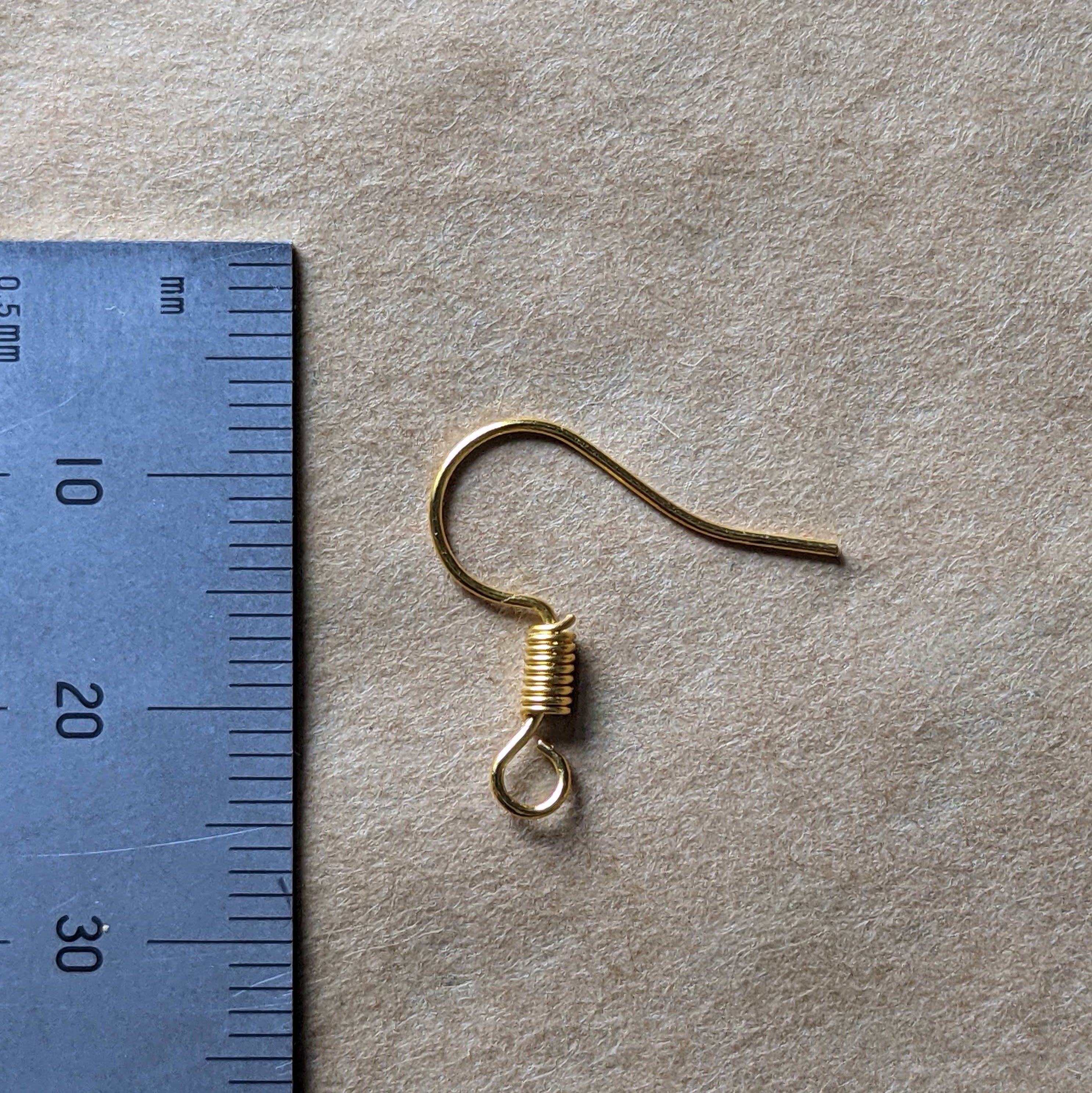
The earwire is attached with jewelery pliers through the hole. The 1mm hole is made for up to 0.8 mm wire over 20 ga. Gold plated french hooks are used. these are commonly available as jewelry findings.
Production Scaling Boards
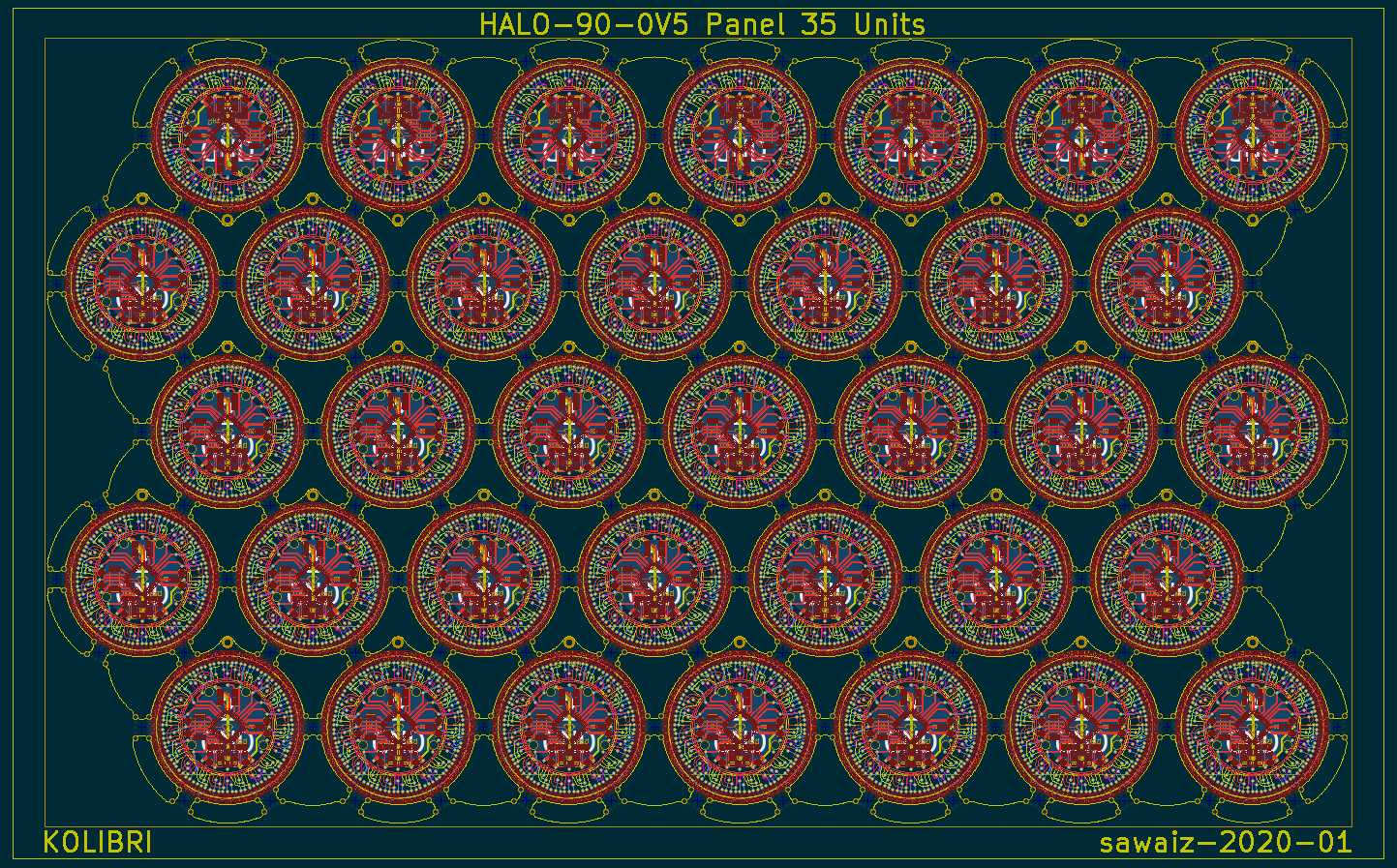
The board can be hexagonally packed into a panel with tiny tabs since it's held on all sides. To increase production efficiency, only one side can be PnP and the battery holder is added afterwards by hand.
Production Scaling Cases
The master moulds can create secondary masters out of resin which could then be used to make gang moulds, allowing for multiple castings in parallel.
![gangMoulds]
Programmer
The programmer has a hole at the top to allow a pin to push the button for testing.
The 3D printed base holds the board in place while the PCB is held to it with 3mm heat set inserts. The PCB acts as a compliant mechanism providing down pressure while still allowing it to be flexible enough to lift.
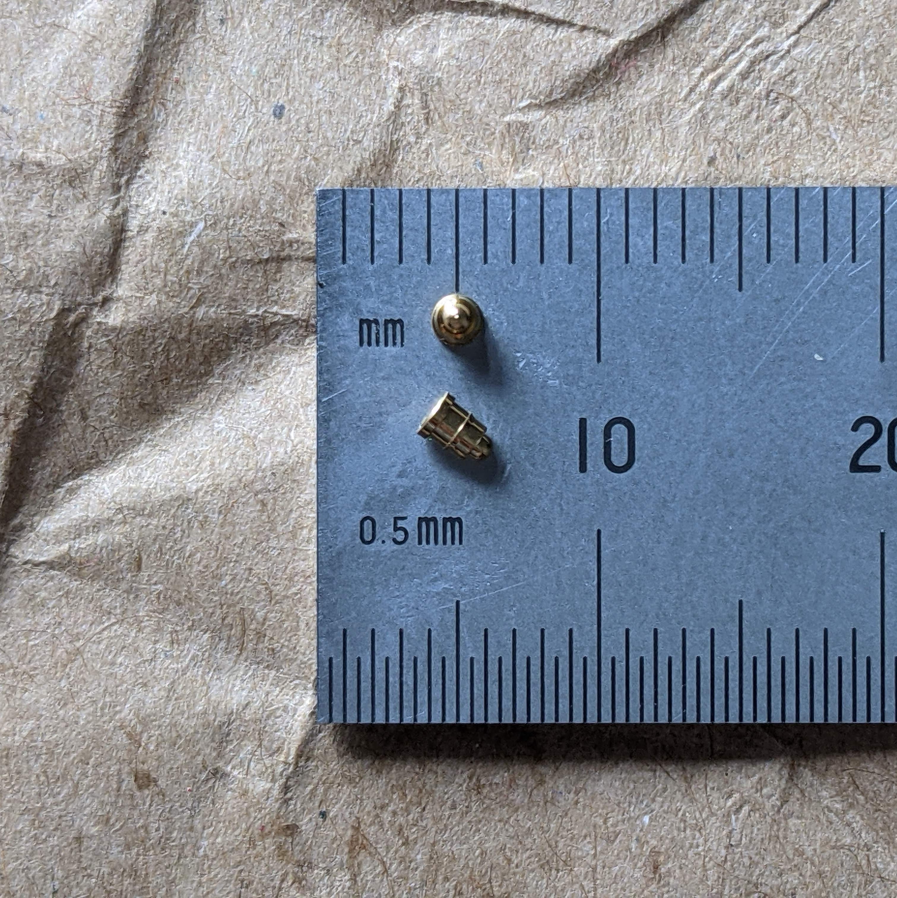
The programmer uses Mill-Max 0965-0-15-20-80-14-11-0 spring pins on a PCB that matches exactly with the six pads on the face of the board.
The top part is lifted up and the assembled board is slipped in. The spring force from the PCB pushes back down on to the pads and can then be left for programing and debugging.
Artwork
The design and layout, the main artwork on the board and the PCB layers and traces, are NOT protected Intellectual Property ("IP"), see LICENSE files for appropriate details. Any additional writing or images such as the Kolibri bird, copyright and designer notices, and certifications ARE considered protected IP and notice is given that they are protected by all applicable IP laws. The below "Getting Started" card also has artwork which is considered protected IP and is copyrighted with all rights reserved.
| Front | Back |
|---|---|
 |
 |
Inventory and QC
Inventory can be managed with QR coded serialized tags. This serialization provides better quality control because it allows failure analysis and tracking in cases of issues traceable to batch and assembly.
Packaging
We are packaging and shippping in 14 cm x 17 cm padded envelopes with branded stampings. These fit under the Warenpost requirements and allow international shipping. The envelopes are verifed to be under 3 cm before dispatching. Custom labeled sleeves will be used for retail packaging.
Shipping
The labels are printed with CN22 on the harmonized label schedule.
Lithium cells have special requirements for shipping. With air mail, small cells (up to four) are packaged securely and may be sent with the product. A note (Lithium metal batteries in compliance with Section II of PI969) is required on the packaging, but no warning label is mandatory.
For international shipping, the HS code 7117.90.0000 Imitation Jewlery other is used.
Safety
The edges are fully routed when possible or finished afterwards. The PCB is made from fiberglass so care must be taken because it can have abrasive edges. Clear coat nail polish can be applied to round and soften the edges without changing how it looks.
The CR2032 cells are quite safe, as they have only very small traces of lithium, and have a fairly high internal resistance. However, they must still be disposed of responsibly. LIR2032 or other rechargable 2032 cells should not be used because they have a higher voltage outside of the guaranteed parameters and significantly lower capacity (under 25%).
If the battery is placed in backwards, it will drain over time because there is no reverse polarity protection. It will heat up but should not damage anything, due to high internal resistance limiting the discharge. The low voltage, 3.0 V, as well as the currents used pose very little risk.
The printed circuit boards are assembled in a lead-free process, and all components are ROHS certified.
Certifications
Certifications take time and effort but will make a better product by guaranteeing its safety to users and letting them use it in other projects. The table below shows the order in which we will obtain certifications.
| Cetrtifing Authority | Status |
|---|---|
| OSHW | DE000103 |
| CE | No (Self Certification) |
| FCC | No (Self Certification) |
| WEEE | No (yearly fee) |
Licence
The product was designed by Sawaiz Syed for Kolibri. Kolibri owns all protected IP. Everything that is not otherwise stated as being protected IP (e.g. firmware, PCB design, documentation) is released under permissive copyleft licenses.
| Sector | License | Verison |
|---|---|---|
| Hardware | CERN-OHL-S | 2.0 |
| Firmware | GNU GPL | 3.0 |
| Documentation | CC BY-SA | 4.0 |
Files of all licenses are required with the distribution of files. All files are available in easy-to-modify formats for remixing.
Please purchase original products from Kolibri to support further products, design, and research :)
Attribution
Fonts
Libraries
- STM8 Headers Copyright (c) - 2020 Georg Icking-Konert
ToDo
- Led sometimes remains on after suthdown
- Randomly HALO pattern forms high low pattern
