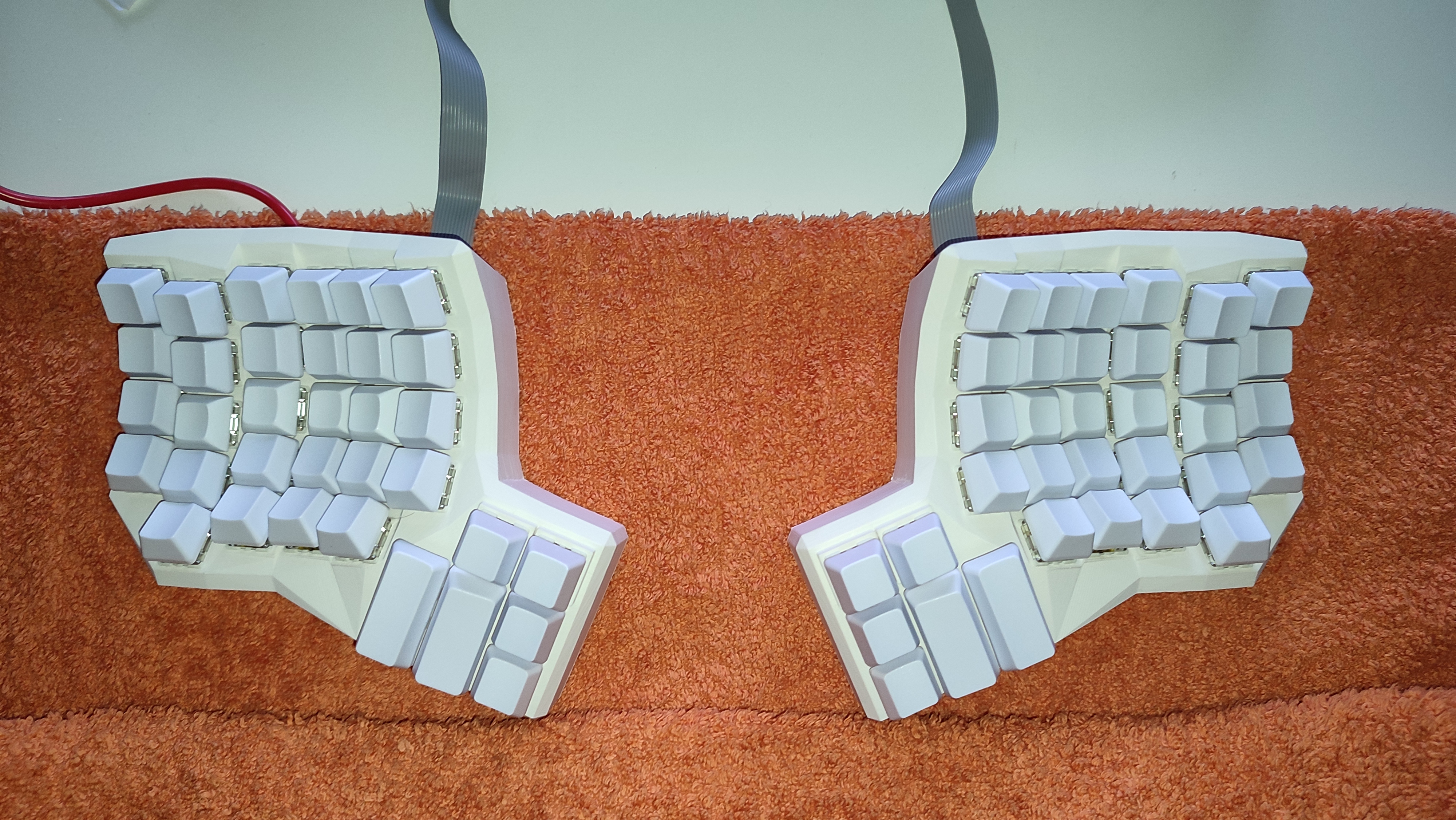
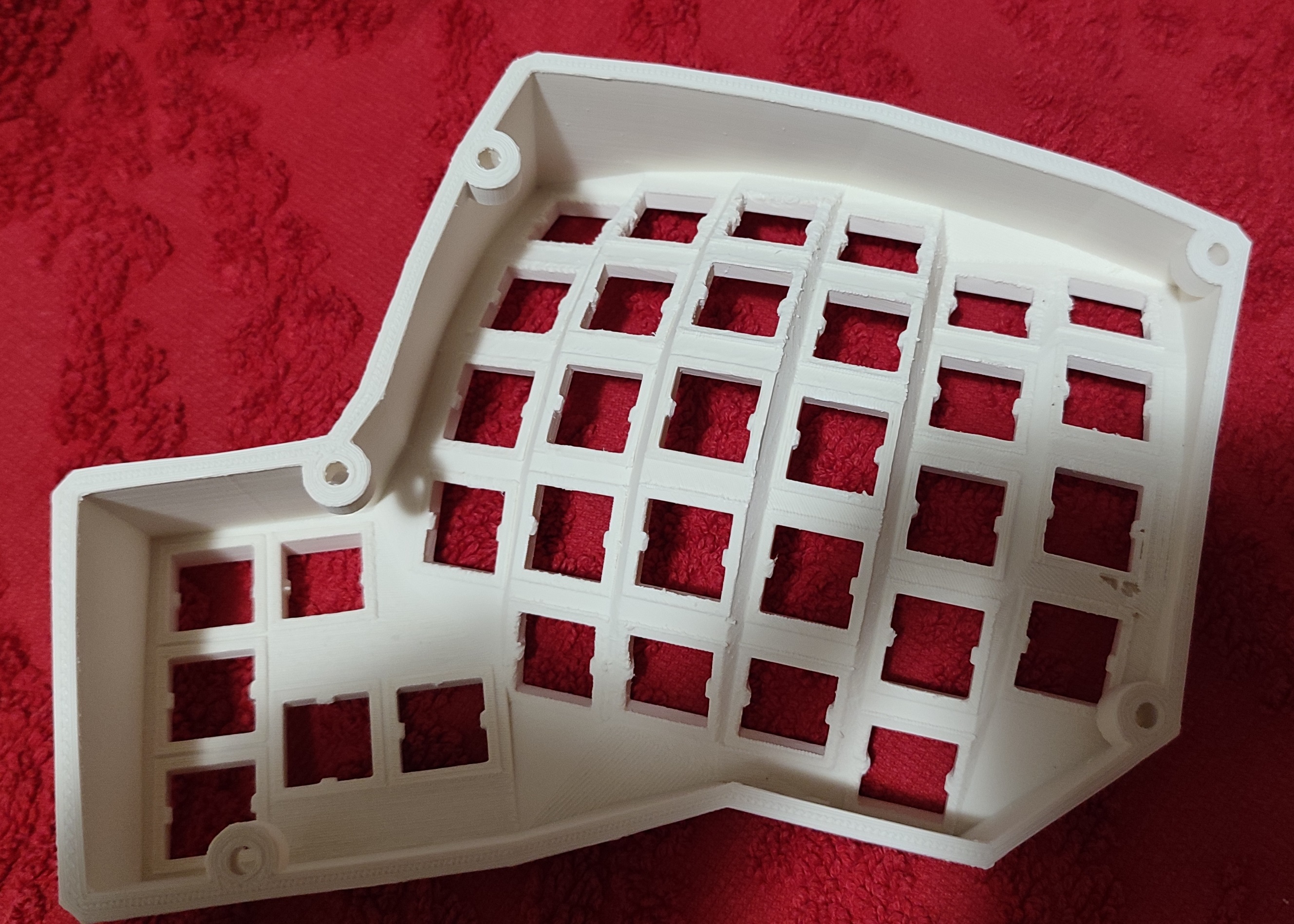
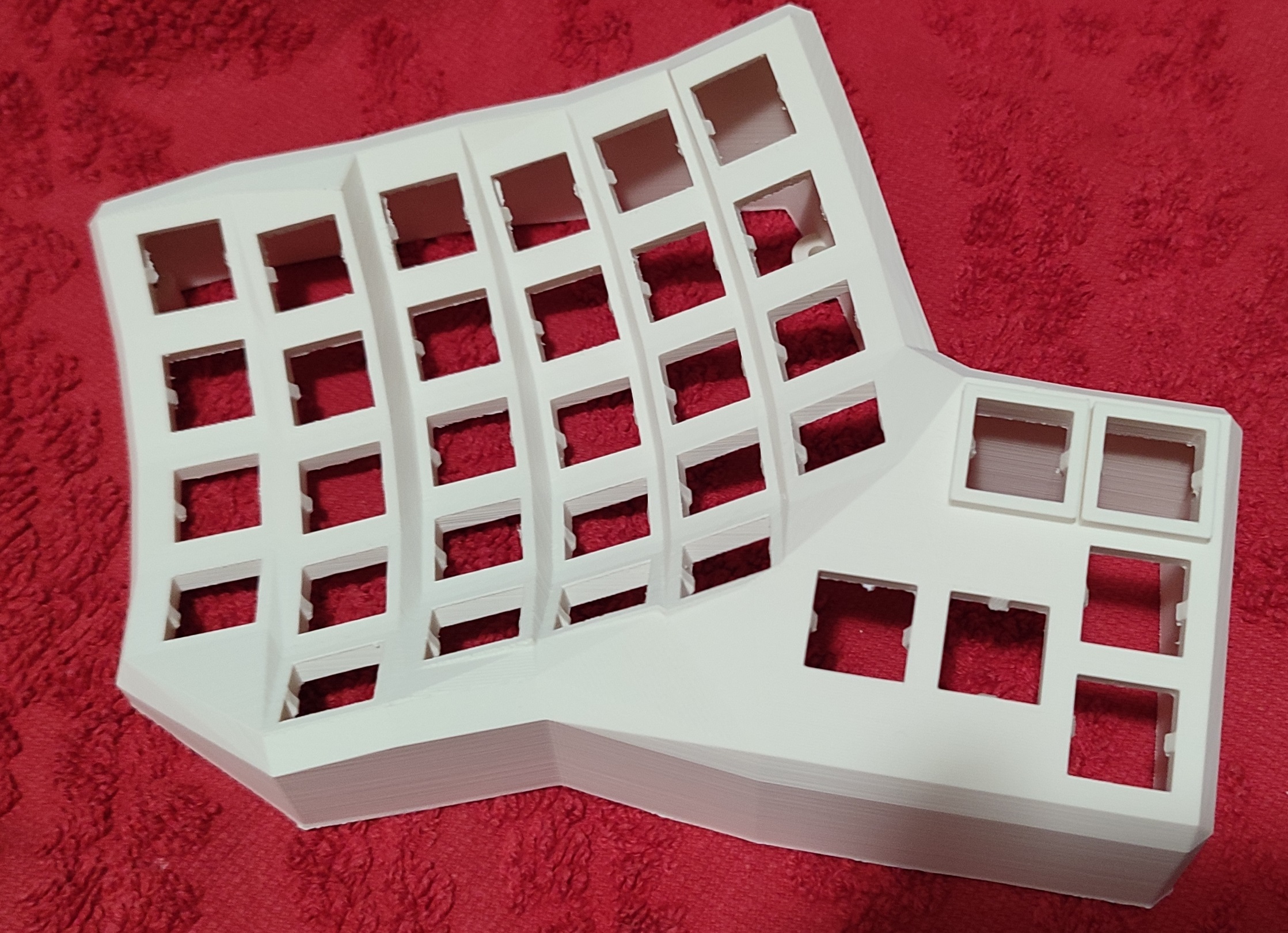
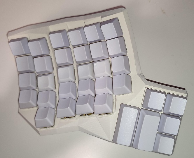
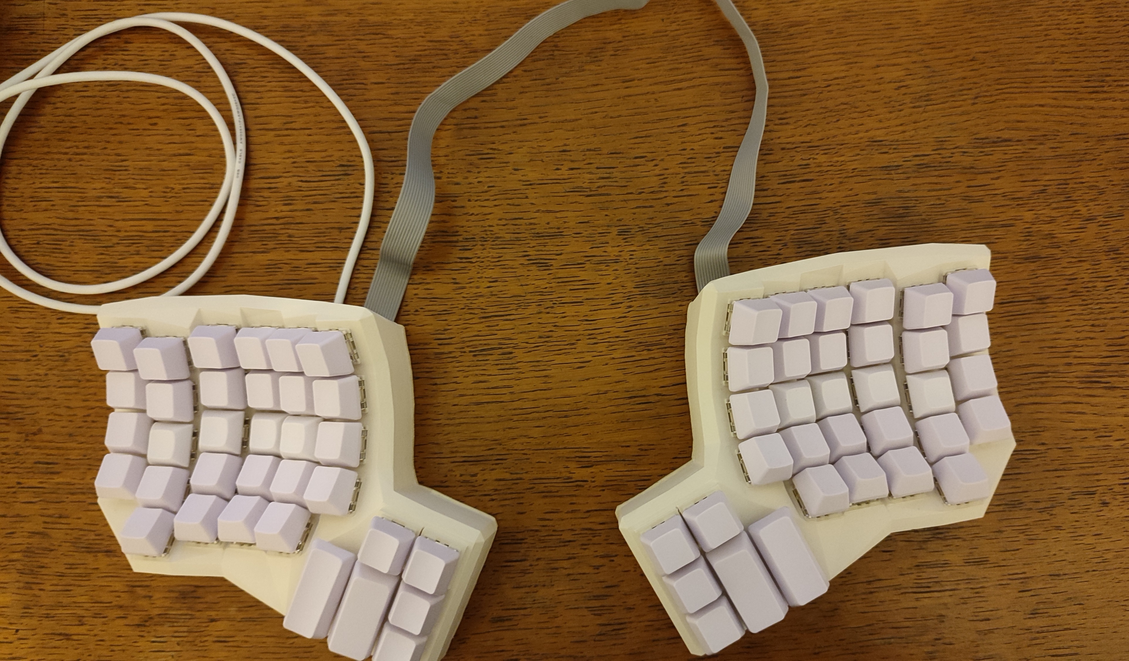
This keyboard is a fork of dactyl-cc.
Differences with dactyl-cc and some notes:
-
Fixed switch hole sizes (if you print the current version of dactly-cc, you will have a bad time).
-
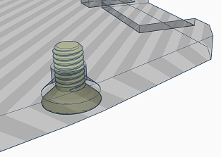
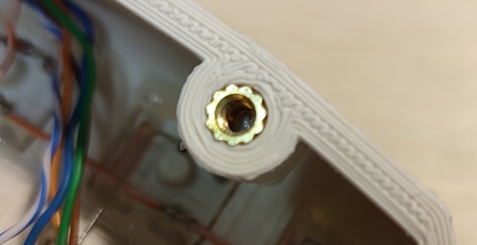
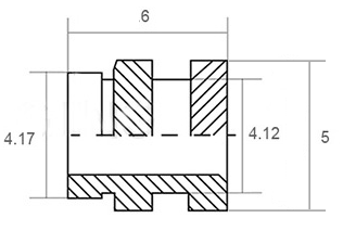
Fixed screw hole sizes for M3 screws and "threaded brass insert" (AliExpress).
-
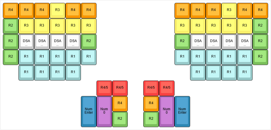
Original Kinesis Contoured keycaps are from ABS and are very expensive (50EUR + shipping). Solution (use OEM and DSA keycaps). Due to different naming conventions for numbering rows, we will define them as
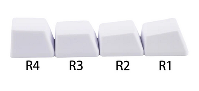
Here is a list of which keycaps you will need (ABS for < 10EUR, PBT < 20EUR):
- 18 pcs of
1x1uOEMR1(ZXCVrow), - 2 pcs of
2x1uvertical OEMR1(≡Numpad Enterkeycap), - 2 pcs of
1x2uhorizontal OEMR1(≡Numpad 0keycap). - 10 pcs of
1x1uOEMR2(ASDFrow), - 12 pcs of
1x1uOEMR3(QWERrow), - 12 pcs of
1x1uOEMR4(1234row), - 4 pcs of
1x1uOEMR5(F1F2F3F4row), - 8 pcs of
1x1uDSA with the deep dish ("blind" keycaps) — you can replace DSA keycaps with1x1uOEMR2keycaps.
The
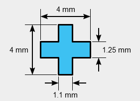
1uOEMR5keycaps are very rare, so we opted forR4keycaps instead. To compensate keycap height difference, we raised the switch sockets/holes by 3mm. The1x1.25uOEMR2s are also very rare so we opted out for1ukeycaps. Note that Cherry stems are not "fully symmetric", therefore if you want to rotate the keycap by 90°, you also need to rotate the switch:Sometimes
Numpad Enterkeycaps have rotated stems (therefore, on the standard keyboard the key switch will be placed sideways). Consult with your keycaps vendor if this is the case (it was in ours). This is important because switch sockets have side nubs. The current version of the keyboard hull has both sockets withNumpad EnterandNumpad 0keycaps rotated.The other option is to 3D print keycaps. We were unsuccessful in FDM printing — it is hard to get the keycap stems right. Probably the best option is to use stereolithography. If you want to generate the 3D models we suggest you look at the Parametric Mechanical Keycap Library.
- 18 pcs of
- Machine Type: Creator 3 Pro
- Material: ASA
- Layer Height: 0.1mm
- Shell Count: 3
- Fill Density: 25%
- Fill Pattern: Hexagon
- Print Speed: 50mm/s
- Travel Speed: 80mm/s
- Extruder Temperature: 250°C
- Platform Temperature: 110°C
- First layer: 0.3mm
- Raft: yes
Due to the long printing time — 50 hours for each side and the small nozzle size, it is very likely that the extruder will get clogged.
-
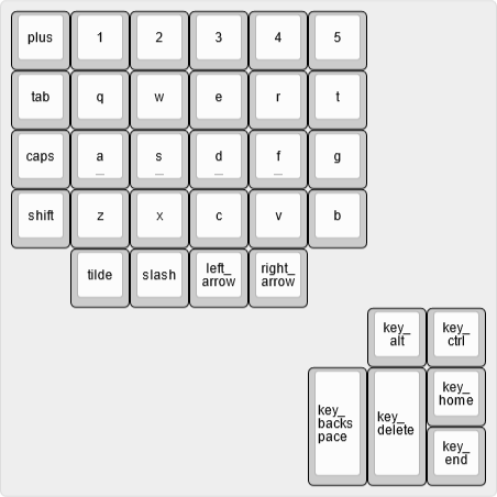
Apply your modification to the code. Here are the labels of the key sockets used in the code:
-
Compile ("requires" CMake).
cd build ./build.sh -
Install OpenSCAD (Development Snapshot is the best choice). Files
.scadwill be generated in the folderbuild. -
Generate STL files.
For measuring distances on STL files we recommend Blender. For post-processing and quick edits, we recommend Thinkercad.
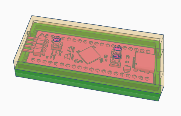
Our choice for the microcontroller is WeAct BlackPill STM32F411CEU6:
In the folder things you can find some custom STLs:
-
Custom bottom plate with recesses for USB cable and 12-wire ribbon cable, and modified holes for M3 flat/countersunk head screws.
-
A case for blackpill microcontroller.
Note. With low RPM you can easily drill into ASA material.
- 2m of an old hard UTP cable (0 EUR)
- an old floppy drive ribbon cable (or any other ribbon cable, 0EUR)
- 10 pcs of 6mm M3 flat/countersunk/Philips head screws (0.5EUR)
- 10 pcs threaded brass insert (1EUR from Aliexpress)
- keycaps (<10EUR for ABS, <20EUR for PBT on Aliexress — contact the store)
- 68 pcs cherry-like key switches. We have bought 110 Gateron Pro Yellow V2 2.0 for 18EUR (good build quality, linear, pre-lubed).
- WeAct BlackPill STM32F411CEU6 (where to buy 7EUR)
- 24-pin female header for the microcontroller
- 100 1N4148 diodes (0.75EUR)
- Soldering iron with adjustable temperature (borrow, otherwise We recommend PINEICL or a cheap one on Aliexpress)
- Solder
- Tweezers with a tiny head
- Wirecutter
- Razor knife
- Scissors pliers for wire stripping (that support small wires)
- USB-C cable
- Multimeter
- Hot glue gun
- Around 25 hours of spare time
- ...
-
Stabilize switches with hot glue.
-
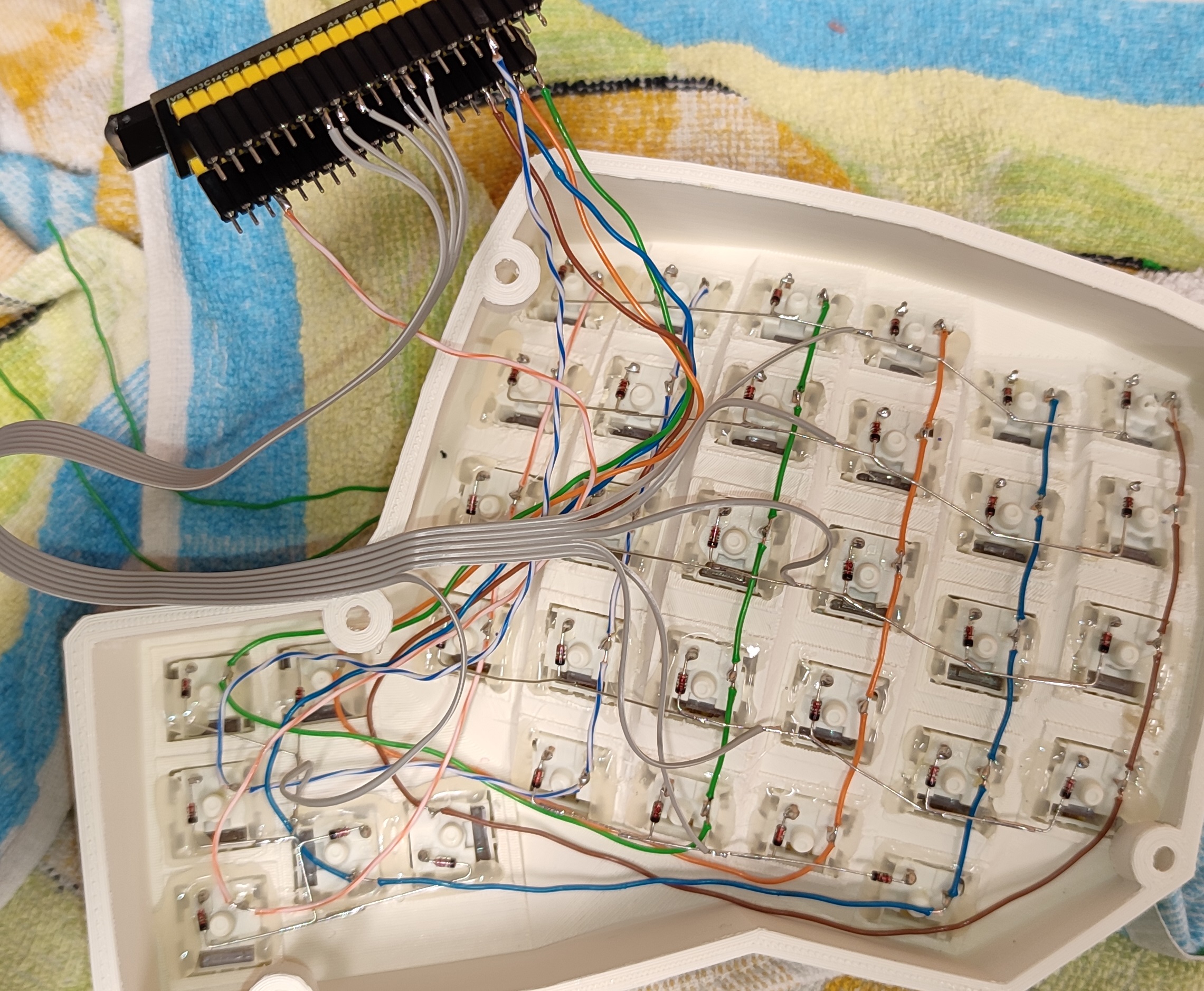
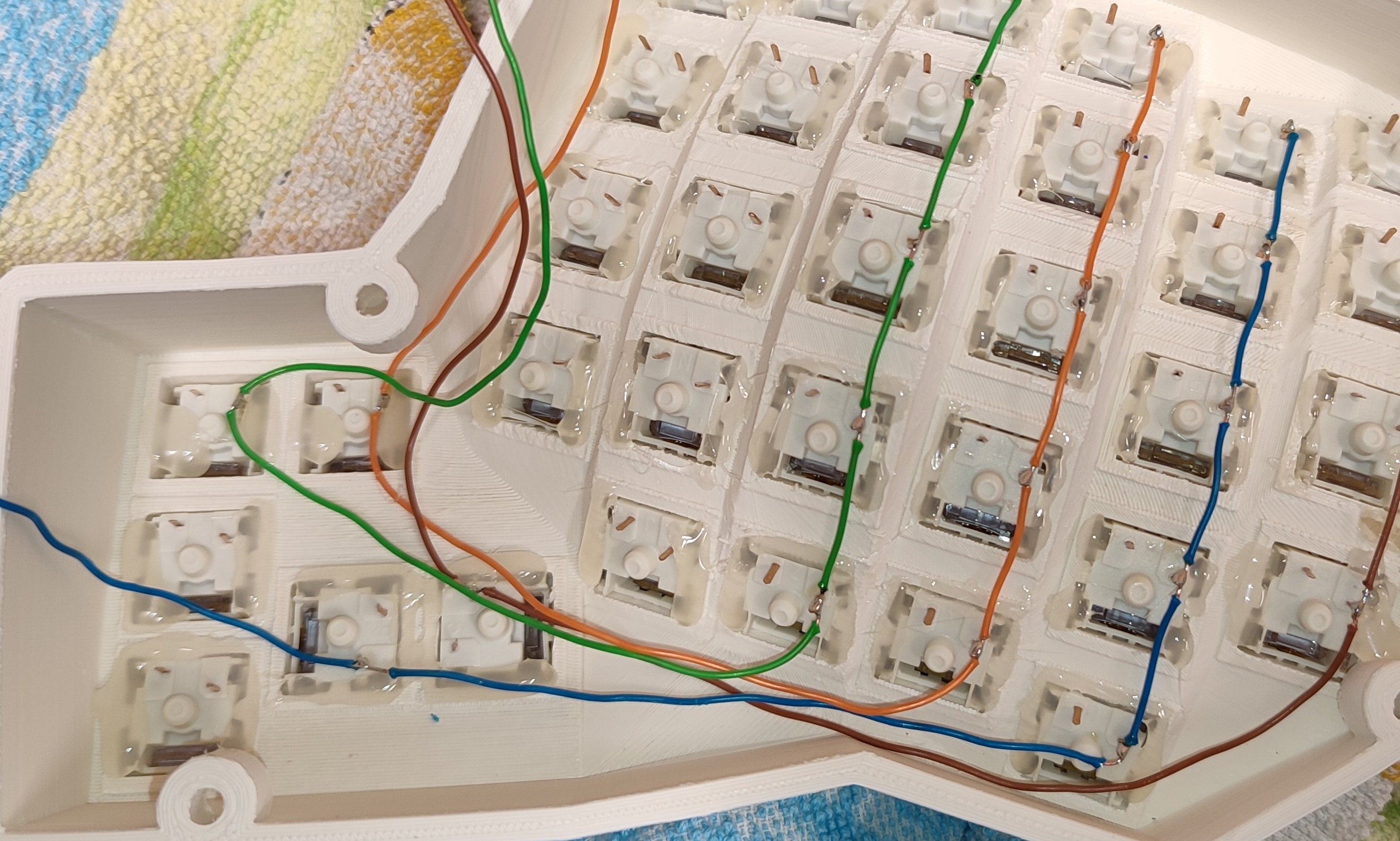
Place wires for the columns (if you start with rows first, it is harder to replace diodes/switches later).
- Extract/unwind wires from the UTP cable
- Make a hook.

- Hook up the wire to the top row pin and mark the position for the rest of the pins.

- Using the scissors pliers for wire stripping cut the insulator for each mark twice. Then use a Razor knife to partially peel off the insulator.

- Remove the rest of the insulator using tweezers.

- Apply flux and solder the column wires to the switch pins.
-
Make rows from diodes (start with making "eyes") — double-check the orientation of diodes.

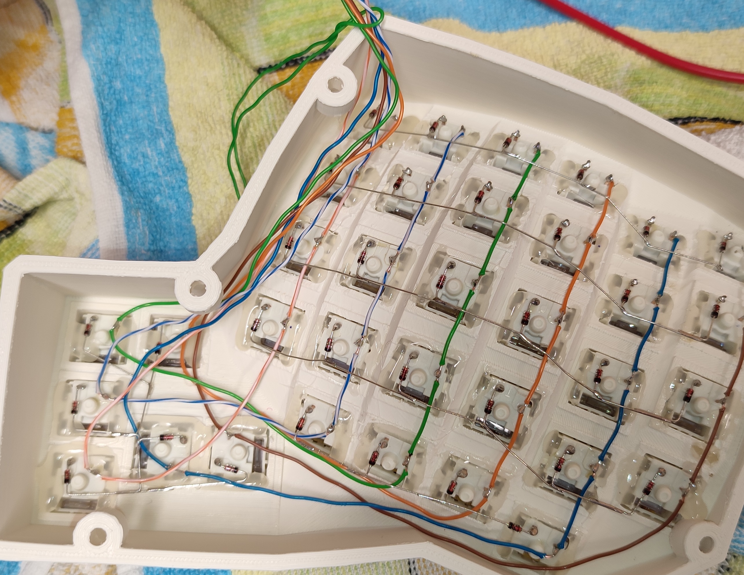
-
Test the left side of the keyboard (flash the microcontroller first).
-
Make the right side.
-
Connect the left and the right side with a 12-wire ribbon (6 columns and 6 rows) cable according to your firmware settings.
-
Connect USB wires to the female header for the microcontroller (
D-→A11,D+→A12,+5V→5V, andGND→G). This will reduce the footprint of the microcontroller inside the keyboard hull. -
Secure the wires with hot glue.
-
Make the bottom plates. Our 3D printer had problems. So we used 4mm plywood with longer (8mm) M3 screws. Here is the design for the wooden bottom plate — bottom_left and bottom_right. These designs do not take into account the ASA shrinkages. You need to do modifications on your own.
-
Use M3 screws to secure the bottom plates
-
Add pads to the bottom plates (you can make them from an old mousepad).
...can be found here — qmk_firmware.
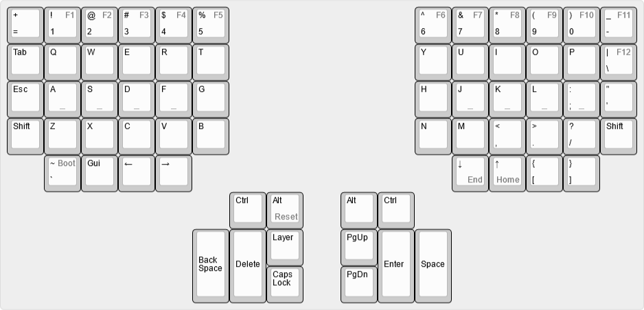
The default layout is:
- To access F-keys use the Layer key.
- Reset the keyboard:
Layer + RAlt - Jump to the bootloader
Layer + `
Nice layouts to check out:
Coming soon.
Coming soon.
Coming soon.
