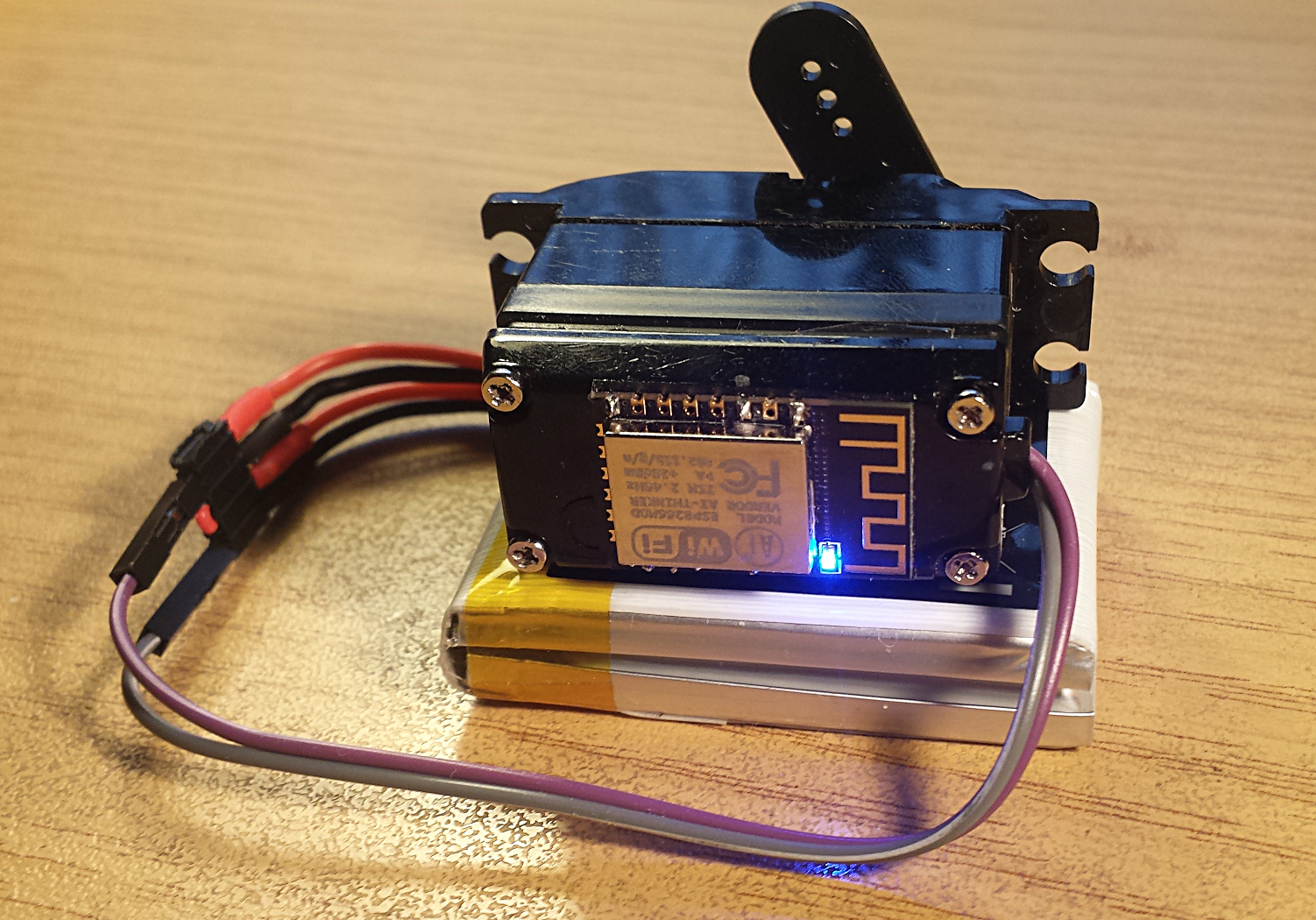
An rc-servo controlled by an ESP8266 via wifi commands.
The ESP is both access point and wifi-station. The station can be configured to join an existing SSID by selecting one of the header files in the wifi-settings folder. Not all header files listed in EspWebServo.ino are found in wifi-settings to protect some real-life credentials. Take the existing ones to model your own header file.
The access-point is always active to reach the device, and to reconfigure the network for the station interface. The access-point's own SSID is configured via AP_DEFAULT_SSID (default 'jw-ESP-ADC', as I was playing with an ESP-ADC device. Please change this). It serves DHCP and has a web-interface on http://192.168.4.1/
The serial console, if connected prints debug output.
The following components were used per unit:
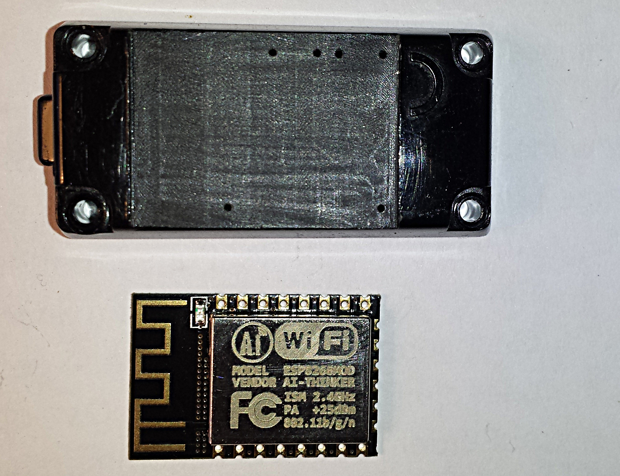
- ESP-12E module from AI-Thinker http://de.aliexpress.com/item/Esp8266-WiFi-series-of-model-ESP-12-ESP-12F-esp12F-esp12-authenticity-guaranteed/32468324806.html
- Standard servo Modelcraft MC410 from conrad.de
- Step down voltage regulator from http://de.aliexpress.com/item/Free-Shipping-5PCS-Ultra-small-power-supply-module-DC-DC-BUCK-3A-adjustable-buck-module-regulator/1727878724.html
- 4x resistor 2K2 1/8W
- 2S liPo 7.4V 1.15 Ah from conrad.de
- 2 Jumper wires male/female
- Connector female 4pin.
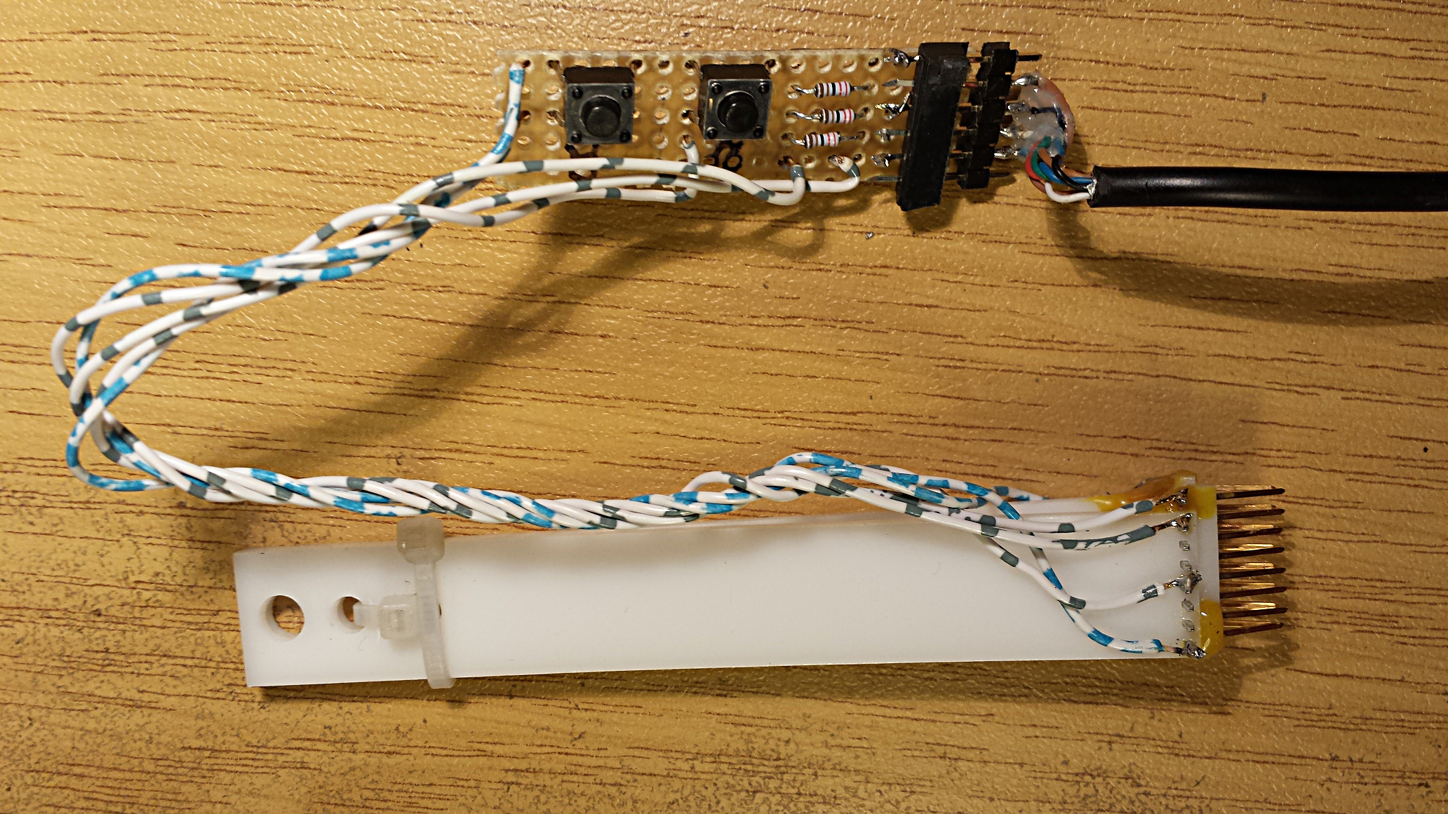
These components are used to build the programmer hardware:
- cheap USB-UART converter.
- 4pin connector male+female to temrinate the uart connector.
- 2 smapp PCB pushbuttons for RESET (right) and GPIO0 (left)
- 3x resistor 2k2 1/8W used as voltage divider on the TxD. This is optional, measure your TxD idle level, if it is in the range 3.2 .. 3.5V you can use a direct connection. Else, or if unsure use a voltage divider like this: Between USB dongle and ESP-clamp there is 2k2 ohm. Between ESP-clamp and GND there is 2x 2k2 ohm in series. ESP modules are not 5V tolerant!
- The clamp is constructed from 2mm acrylic sheets lasercut, fixed with zip-ties and hot glue. It basically works, but is difficult to put in place.
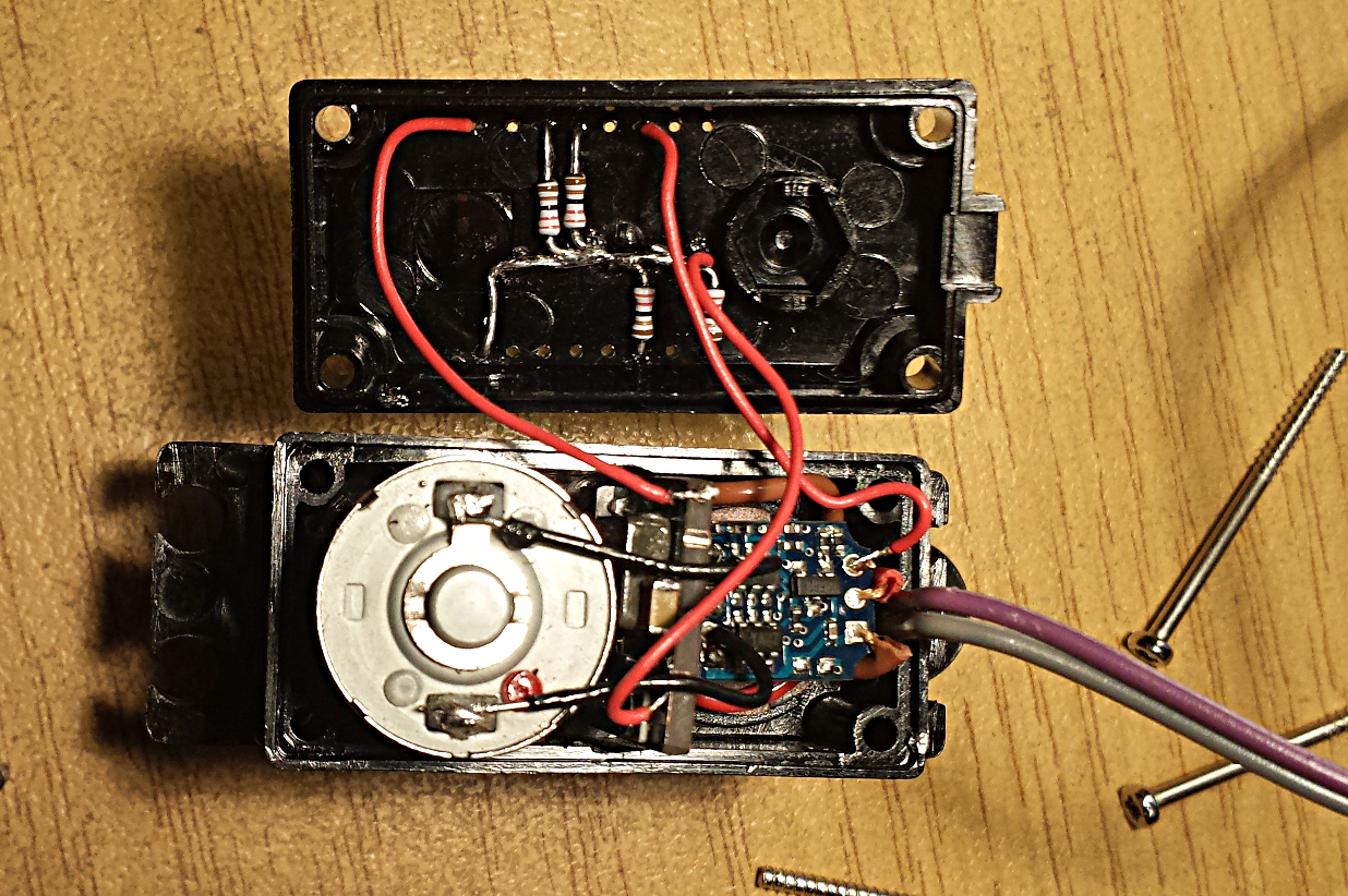
Lipo:
- My lipo came with a big connector (4pin, 4mm pitch, male(!)) - This was replaced with a 4pin female pitch 2.5mm.
Servo:
- The standard 3pin female servo connector was replaced with the two male ends of the jumper wires, to connect to the servo.
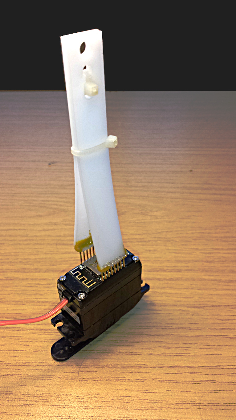
- The housing was prepared to mount the ESP-12 Module using a milling machine. Diameter of the holes is 0.6mm, pitch is 2mm and 14mm across. The back side was leveled down by 0.7mm for a perfect fit of the the Module. Not really necessary. See drawing and photos.
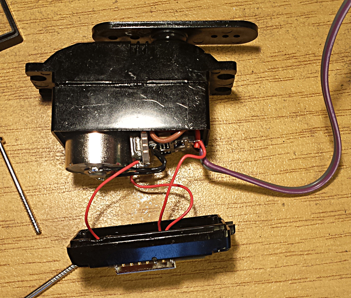
- The step down converter is inside the servo, we clear a gap 4mm wide, 15mm long between motor and potentiometer to accomodate the converter. The converter is too big to fit.
Step down converter:
- The input and output capacitors are removed.
- The PCB is cut back on both input and output side by ca 1.5mm each. We cut right though the holes.
- input and outcapacitors are soldered back in place so that they do not extend beoynd the PCB.
- The converter needs to be adjusted before soldering. Apply 7.4V input, connect a voltmeter to the output adjust the onboard potentiometer so that the voltmeter read 3.33V.
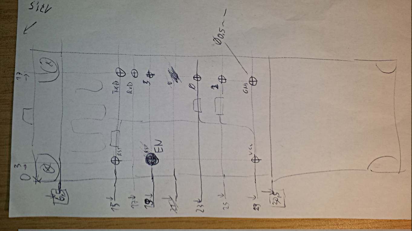
The servo supply directly comes from the 7.4V lipo cells. The servo input is connected directly to GPIO5 of the ESP-12E module. The ESP-12E module gets its power from the step down converter. The converter is The ESP-12E module needs specific external components before it works normally. GPIO0, GPIO2 need a pullup to 3.3V, GPIO15 must be connected to GND. The reset (RES) and enable (EN) pins should also have a pullup for stable operation.
An external upload circuit is built to snap on the left and right row of 8 pins of the module.
Note: The current model of the clamp has rather weak contacts. TxD -> RxD, RxD -> TxD is correct, although there are comments in the forums stating the opposite. If the serial line upload does not work reliably, soldering direct wires for GND, RxD, TxD is recommended.
With these 4 pullups an one GND connection, the module starts. A brief bliiink-blink is seen on the blue led of the module when poweing up. It gets slighly warm and the lipo delivers ca. 38 mA. The module starts a WLAN access point, named AI-THINKER_DC27D0. (Without connecting GPIO15 to GND, the lipo only delives 18 mA, and the module is inactive). The led shows an occasional blink blink, while a WLAN client is connected to the access-point.
When the station connects to an existing network, it tries to reach the time server configured as NTP_SERVER_NAME (default 'time.nist.gov'). After a first success, the device has a real-time clock, and prints the time every 5 seconds on the debug output. CAUTION: Sometimes it takes several minutes to connect to a network. This only happens if the diagnostics (through the programmer clamp) is not connected.
CAUTION: The accesspoint mode alone does not work reliably. The servo only initializes after the device succeeds in connecting to a network. The blue led of the ESP module lights up, when the servo is powered.
The servo can be moved by accessing e.g.
- http://192.168.4.1/servo?id=1&pos=0
- http://192.168.4.1/servo?id=1&pos=90
- http://192.168.4.1/servo?id=1&pos=180
The network for the station can be reconfigured with e.g.
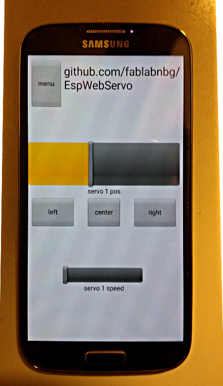
The web interface also has a nice javascript slider to control the servo, and an admin form to control the configuration. The web interface is identical on both access-point and station. You can choose any.
Port 9876 (on both IP-Addresses, access-point and station) is also active with a simple TCP protocol for use with e.g. RoboRemo:
- servo 1 pos 0
- servo 1 pos 180
- servo 1 speed 255
- servo 1 speed 0
Happy hacking!