Pomodoro
A custom built timer for the pomodoro technique.
Use it
- One click starts a 25 minutes work counter. Five yellow LED indicates how many slices of five minutes are left. There is a discrete beep when the timer expires. The LED then flashes to remind you to go into rest mode.
- A second click starts a 5 minutes rest counter. A red LED is turned on. There is a discrete beep when it expires. Then the timer turns off.
- If you wish the turn the timer off during rest mode, click a third time the button.
Build it
Bill Of Material
- 1x ATtiny85
- 5x LED yellow, SMD 0805
- 1x LED red, SMD 0805
- 3x 22 Ohm Resistor, SMD 0805
- 2x 1K Ohm Resistor, SMD 0805
- 1x NPN BJT transistor, SOT-23 (BC846CMTF)
- 1x 1mH Inductor, SMD 1007
- 1x Buzzer, SMD mouser
- 1x CR2032 coin cell holder, SMD mouser
- 1x Tactile switch, SMD EVQ-Q2 mouser
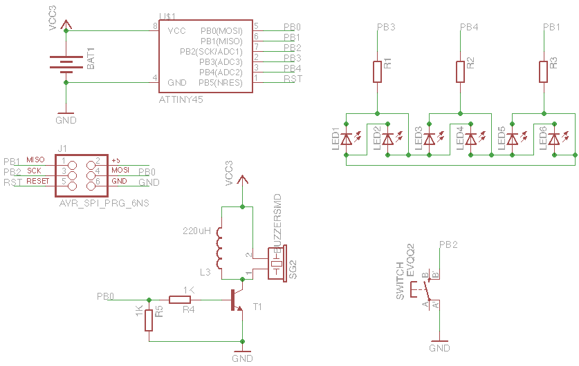
Schematic
Etch the PCB
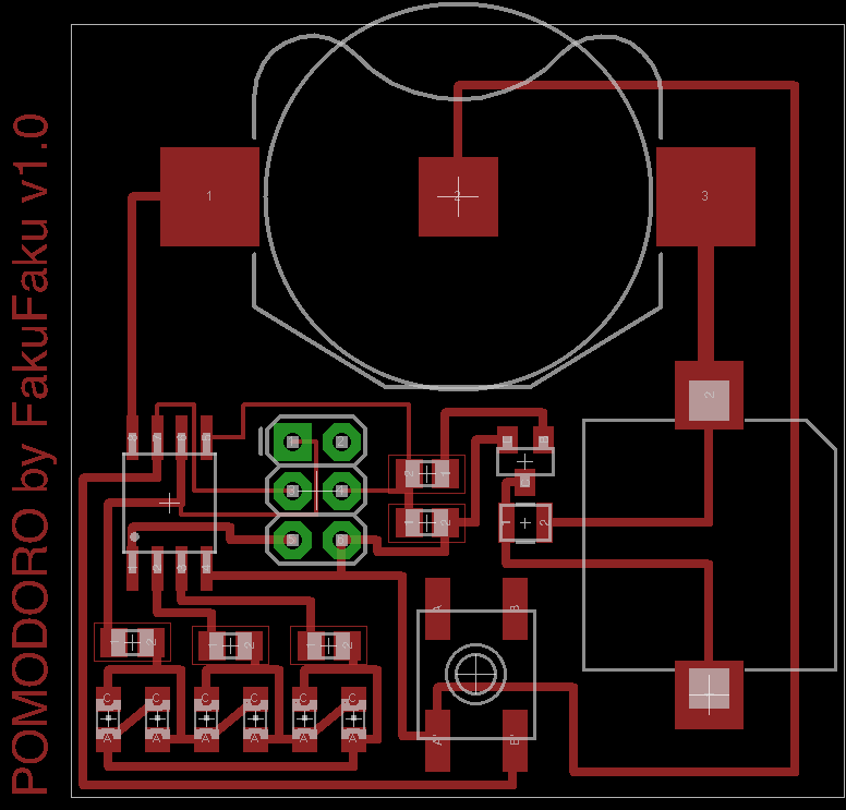
The PCB can be etched using the mask provided in EPS format. Here is a picture of the layout.
Firmware
The firmware is in the firmware folder. It can be uploaded using avrdude and
a usbtiny-isp, for example. The idea is
to press a six-pin header againt the PCB directly when programing. Some spring-loaded
pins would be ideal for the job. The square pad is pad number one of a six-pin ISP
header.
To compile and upload (assuming you have avr-gcc and avrdude installed), type the following in a terminal.
make avrdude
The Code
My goal was to use explore the possibilities of the ATtiny85 microcontroller. We use it here as a timer that first counts 25 minutes (work time) and emit a signal. Then, we can start a second counter for 5 minutes (rest time). Here is what we use.
- A tactile switch connected to the INT0 of the avr as the sole user input. We use it to turn the counter off and switch between different modes.
- A buzzer to give a discrete signal when the timer expires. The buzzer is driven by TIMER0 in PWM mode at 4 kHz, 50% duty cycle.
- As many LEDs as possible to indicate the progress of the timer. By default,
the ATtiny85 has 5 GPIO pins (we could add an extra one, but would lose ISP).
We have thus 3 GPIO remaining.
We assign all of them to LEDs and using charlieplexing, it is possible to drive 6 LEDs using only 3 pins. We choose 5 yellow, for every 5 minutes slice of the first timer, and a single red one, for the rest time of the second timer.
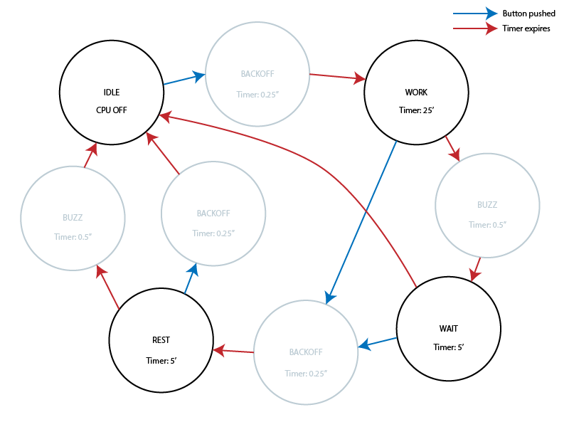
The code is completely interrupt driven. TIMER1 and its overflow interrupt are used to keep track of time during each state. The tactile switch triggers an interrupt to wake up the avr, or switch between states. The finite state machine looks like this. Blue arrows are state switching triggered by a push on the button. Red arrows are switching caused by the timer expiration.
The main states are black circles. The grey circles are the transition states.
It was important to add the BACKOFF state to debounce the tactile button because it triggered multiple interrupts.
License
2014 (c) Robin Scheibler aka FakuFaku
"THE BEER-WARE LICENSE" (Revision 42):
<fakufaku@gmail.com> wrote this file. As long as you retain this notice you
can do whatever you want with this stuff. If we meet some day, and you think
this stuff is worth it, you can buy me a beer in return -- Robin Scheibler


