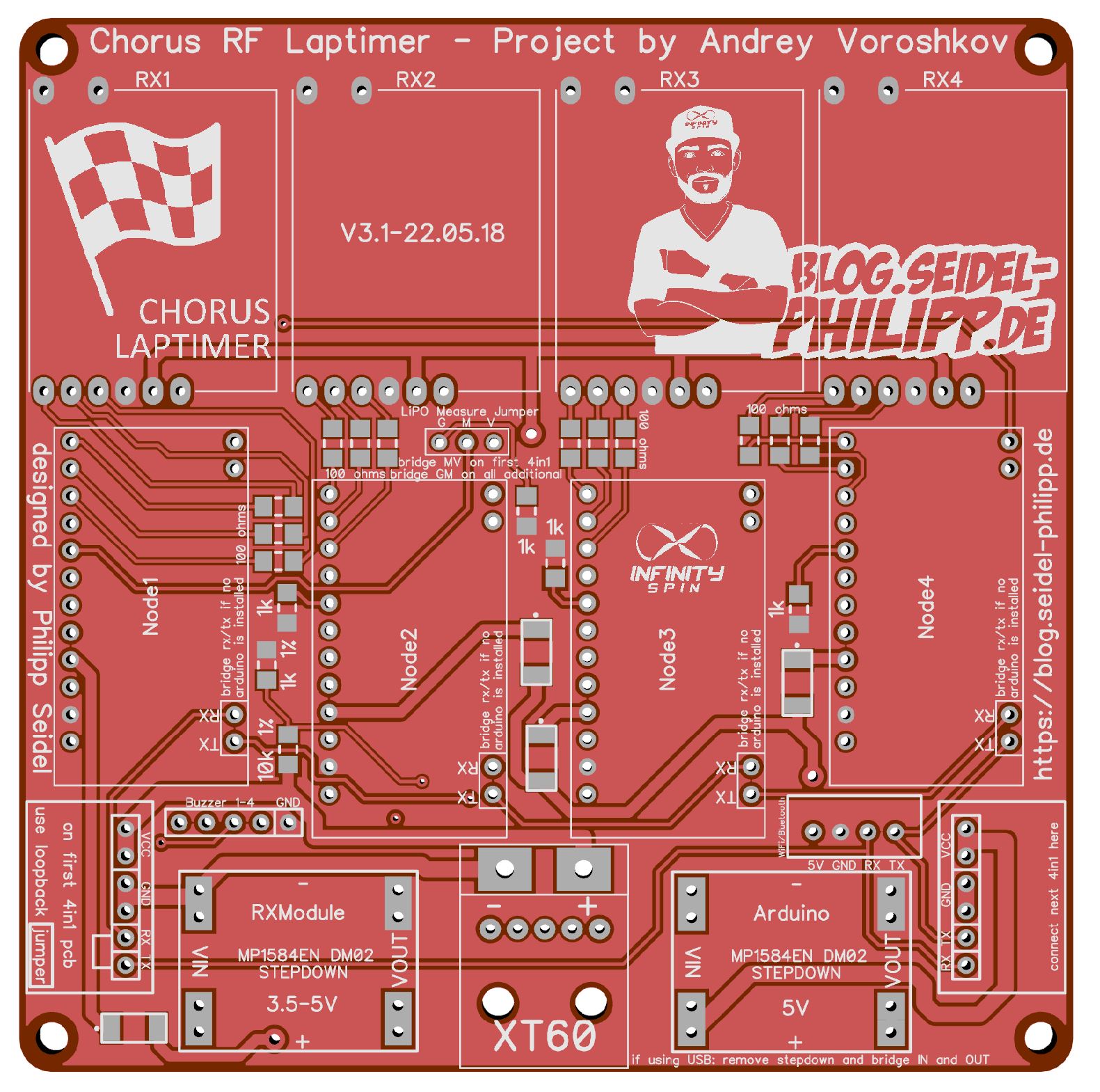
4in1 PCB for the Chorus RF Laptimer by Andrey Voroshkov https://github.com/voroshkov/Chorus-RF-Laptimer

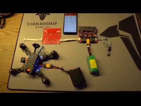
https://www.youtube.com/watch?v=avLRJ5z0UP4
- PCB for 4 Nodes (4 Pilots)
- easy extendable via JST XH cable (8 Pilots)
- 5V stepdown for Arduinos
- adjustable stepdown for RX Modules (use 3.5V to keep temperature low)
- 92 x 92mm mounting holes
- XT60 PowerIn
- 5V USB PowerIn (if you want to use a powerbank)
- stacked hardware - can be changed in seconds
- Buzzer Port to connect one Buzzer per Node
22.05.2018 - v3.1 beta released DOWNLOAD
- inital release
- i did not tested this PCB. To V3.0 i just added the Diodes and did cleaned it up a bit. V3.0 worked so far. Please report any issues!
You can also just use one or two nodes. All you haveto do is bridge TX/RX (see on silkscreen) of the other nodes Always use at least "Node1" because the voltage measurement is connected to this node.
if you want to power the unit via 5V USB, please remove stepdown "Arduino" and bridge IN and OUT.
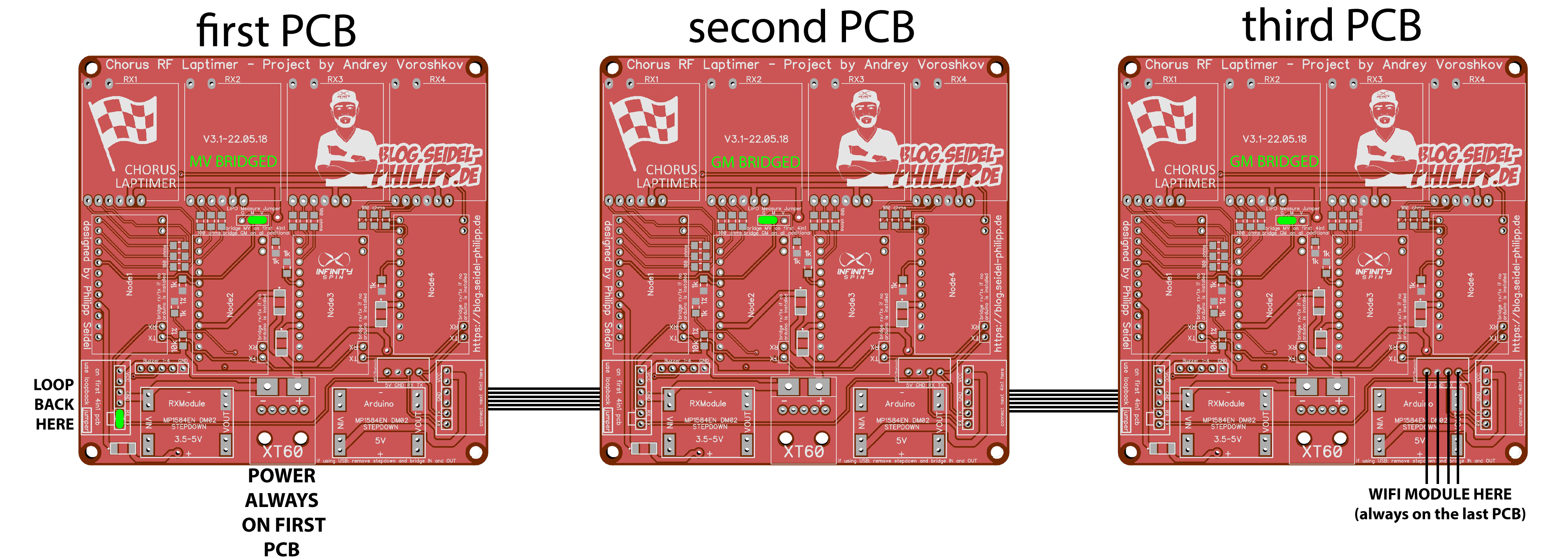
If you plan to connect more PCBS together, please alsways set the Loopback Jumper to the first PCB
Then connect the next PCB via 6Pin wire. On the first PCB, bridge MV. On following PCBs please bridge GM. WiFi Module always connects to the last PCB.
- 1x 4in1 PCB
- 4x Arduino Pro Mini
- 4x RX5808 (with SPI mod)
- 12x 100 ohm 1206 SMD Resistor
- 4x 1k ohm 1206 SMD Resistor
- 1x 10k 1% ohm 1206 SMD Resistor
- 1x 1k 1% ohm 1206 SMD Resistor
- 4x 1n5817 smd 1A 20V do-214ac Schottky diode
- 2x 6 Pin JST XH 90° Connector
- 1x USB Breakout Board
- 2x Pin Jumper
- 1x DT-06 WiFi Module
- 1x 5V Stepdown
- 1x adjustable stepdown
- optional 6Pin JST XH cable for connecting two or more PCBs together
- 1x XT60
- 4x 3Pin Pin Header Socket
- 4x 6Pin Pin Header Socket
- 4x 12Pin Pin Header Socket
- 16x 2Pin Pin Header Socket
- manny Pin Header RM 2.54
(some links are affiliate links)
https://github.com/voroshkov/Chorus-RF-Laptimer
you can order the PCB in china:
- Go to www.seeedstudio.com
- Upload gerber file
- choose PCB color
- add to cart
- order
Detaild Tutorial how to order from seeedstudio here