talkiepi
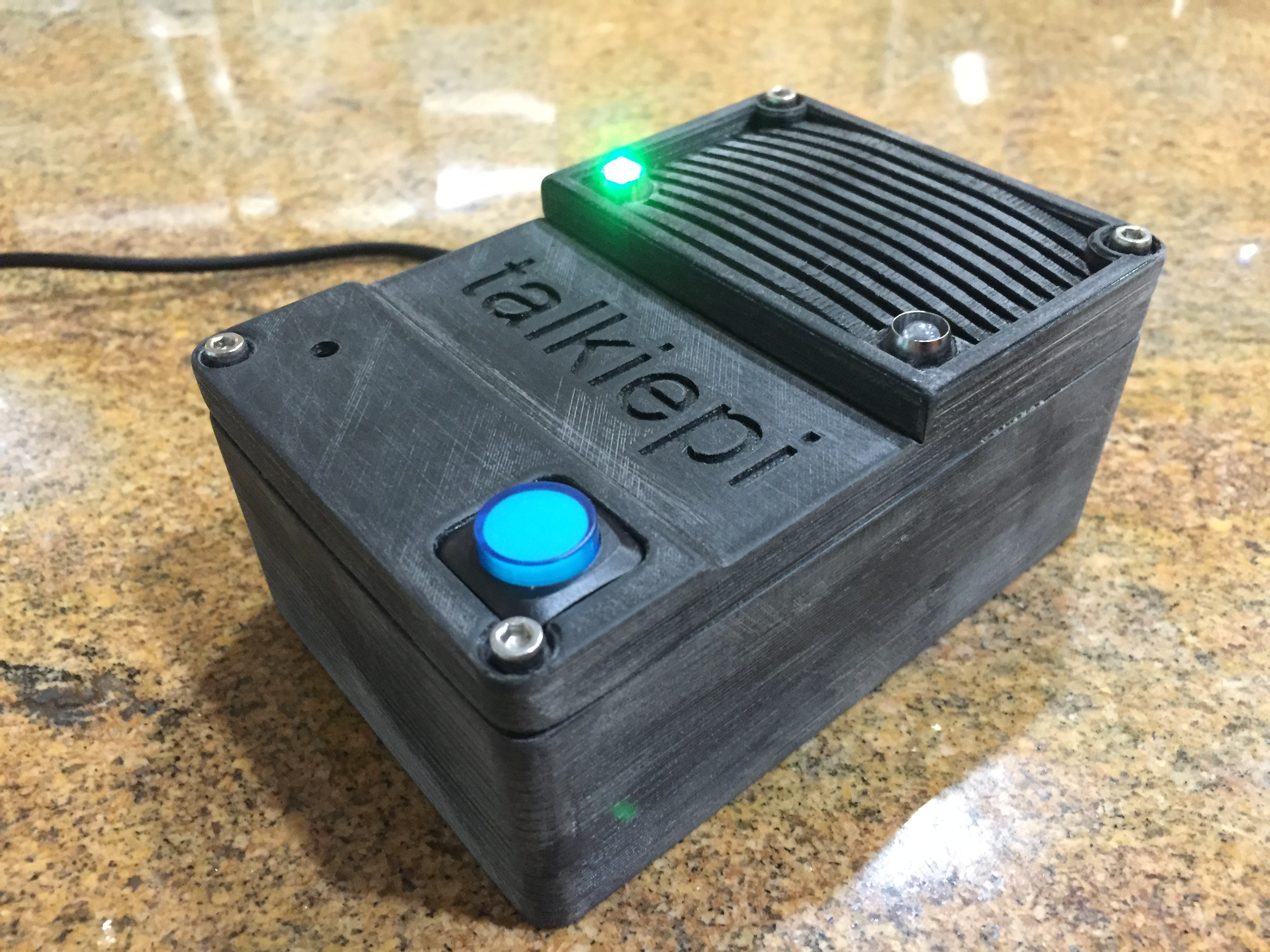
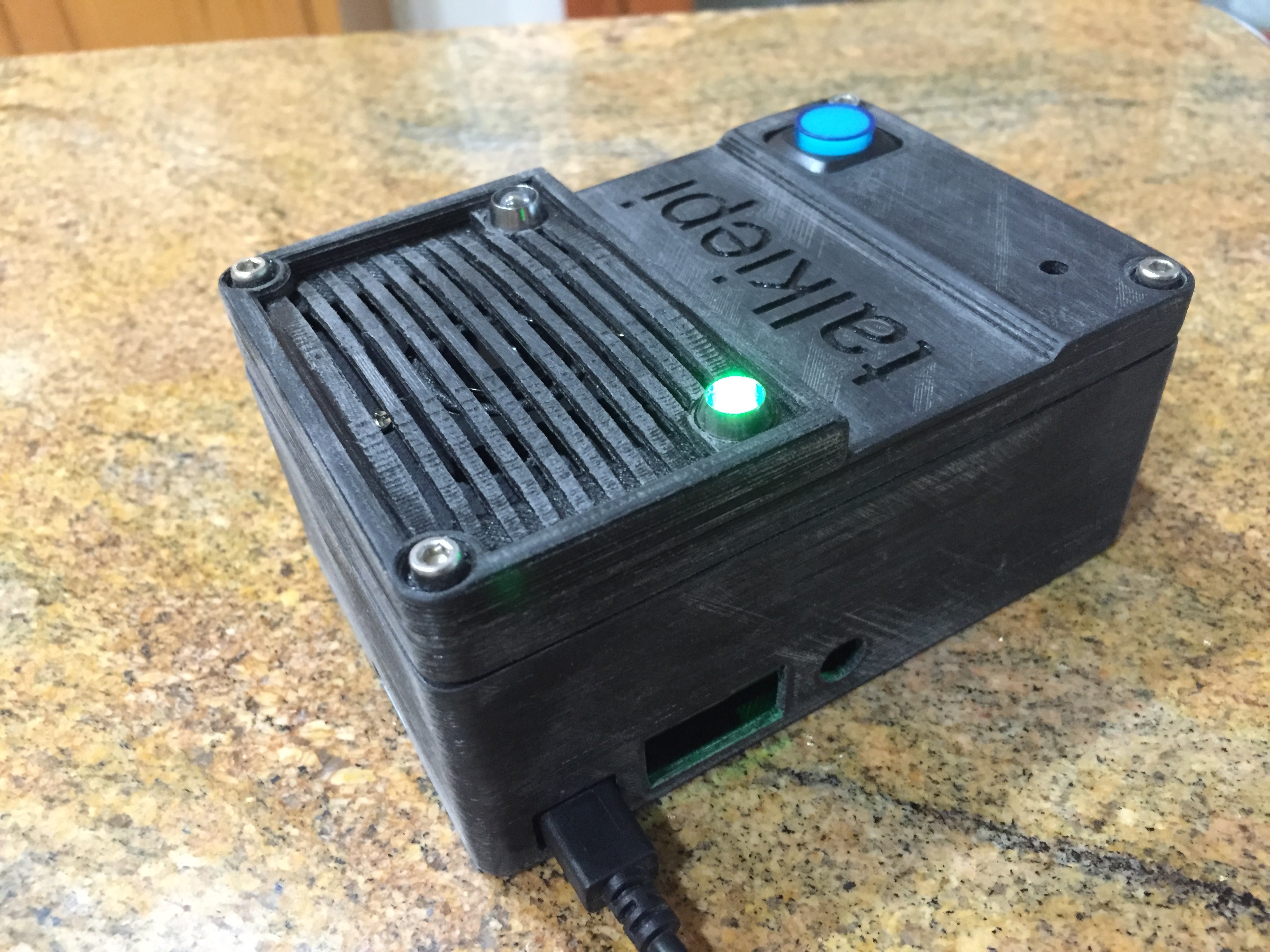
talkiepi is a headless capable Mumble client written in Go, written for walkie talkie style use on the Pi using GPIO pins for push to talk and LED status. It is a fork of barnard, which was a great jump off point for me to learn golang and have something that worked relatively quickly.
3D printable enclosure
In the stl directory are the stl files for the enclosure I have designed specifically for the Raspberry Pi B+ board layout (I am using a Raspberry Pi 3 Model B) and the PCB and components from the US Robotics USB Speakerphone. I will be posting a blog post shortly with a full component list and build guide. For more information regarding building a full talkiepi device, go check out my blog at projectable.me.
Installing talkiepi
I have put together an install guide here.
GPIO
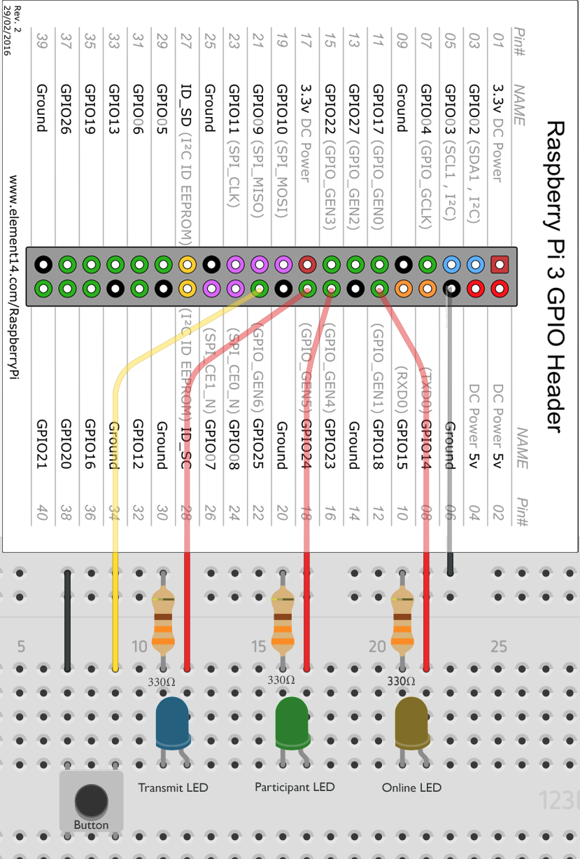
You can edit your pin assignments in talkiepi.go
const (
	OnlineLEDPin        uint = 18
	ParticipantsLEDPin  uint = 23
	TransmitLEDPin      uint = 24
	TransmitButtonPin   uint = 25
)
Here is a basic schematic of how I am currently controlling the LEDs and pushbutton:
Pi Zero Fixes
I have compiled libopenal without ARM NEON support so that it works on the Pi Zero. The packages can be found in the workarounds. directory of this repo, install the libopenal1 package over your existing libopenal install.
License
MPL 2.0
Author
- talkiepi - Daniel Chote
- Barnard,Gumble Author - Tim Cooper (tim.cooper@layeh.com)
=====
RasPi stage intercom
RasPi stage intercom is a wired and wireless stage intercom system. It used a headless Raspberry Pi in a 3d printed enclosure as a belt pack, communicates via wired Ethernet (ability to power the Pi via Power Over Ethernet) and/or regular Wifi with a local mumble server. The Mumble client is written in Go. The project is based on the talkiepi, a walkie talkie style use off the Pi. Both use GPIO pins for push to talk and LED status. The Mumble client is a fork of barnard, which was a great jump off point for me to learn golang and have something that worked relatively quickly.
3D printable enclosure
In the stl directory are the stl files for an enclosure for the Raspberry Pi 3 Model B You will also need a a random USB sound card (to have a microphone input) and a headset + power supply. (PoE to micro USB extractors exist to only require the one Ethernet cable and no local power supply or power bank)
On the top side are 3 holes for 3mm LEDs in LED-fittings or 5mm LEDs without. The big hole is for a 19mm illuminated Push-To-Talk button.
I do recomment Dupont connectors and the proper pliers instead of soldering the cables to a single connector. This way all wires can be removed in case you want to rehouse the electronics into an improved enclosure.
Generation 1:
Next to it is a 2.5mm TRS connector for an external Push-To-Talk button. You can use an M6 thread-cutter in the 3D printed plastic to make it screw in perfectly.
Generation 2: (in development)
On the underside, there is a hole for a round 6 pin mini-DIN socket. It is less prone to false signals compare to TRS. Each function uses 2 pins. 1+2=GND 3+4=INPUT 5+6=VCC
There is a square hole in the side for volume +/- controls.
I used Marquard model 1838.1402
https://www.marquardt-shop.com/de/produkte/schalter/wippschalter/1830/1838.1402/zeichnungen.html
Other changes:
There is enough space for a battery-hat on top of the Raspberry. The Power over Ethernet -extractor no longer blocks the internal sound card. (unused here but can be used e.g. to output an LTC timecode for cameras.) Emergency access to the power-socket is easier. (In case som other power source needs to be connected RIGH NOW.) The audio output of the raspberry sound card (that has no microphone input) is accessible. The LEDs are labeled. The Pins to connect each LED and button to are also labeled on the inside.
Installing
Because Github as a file size limit and because I could not keep it updated, I do not offer an SD-card image. When building your own image (Also see the Talkipi readme.md about that. It should be based on at least raspbian-stretch-lite), try to keep everything that is device-specific (IP-address, mumble user name, server-ip+password,...) in /boot, so it can be accessed from any random computer that can read and write FAT. You should have the filesystem read-only by default, so the box can be switched off in any state.
For the manual installation onto an existing Raspberry Pi, there is an install guide here. There is a script INSTALL_INTERCOM that does nearly all of these steps.
In addition you can use GPIO 14+15 (pin 8+10) for volume+/volume- keys. Just copy VOLUMEKEYS_SERVER.txt and INTALL_VOLUME_KEYS into /boot (the root of the FAT-partition) and execute INTALL_VOLUME_KEYS as root.
GPIO and LEDs
Pins used: (single row only, so no dual-row connectors are needed)
- 2 = (unused +5V)
- 4 = (unused +5V)
- 6 = GND (for volume)
- 8 = GPIO 14 RESERVED for "Volume+" button
- 10 = GPIO 15 RESERVED for "Volume-" button
- 12 = GPIO 18 = +3.3V for "Online" LED
- 14 = GND (for LEDs)
- 16 = GPIO 23 = +3.3V for "Participants" LED
- 18 = GPIO 24 = +3.3V for "Transmit" LED
- 20 = GND (for PTT)
- 22 = GPIO 25 = Push To Talk (PTT) Button input with pull-up
- 24 = (unused GPIO 8)
- 26 GPIO 7 = +3.3V for a second "Transmit" LED (PTT buttons with build-in LEDs)
- 28 = (unused I2C)
- 30 = GND (for external "Transmit" LED)
- 32 = GPIO 12 = +3.3V for a second "Transmit" LED (PTT buttons with build-in LEDs)
You can edit your pin assignments in talkiepi.go
const (
	OnlineLEDPin       uint = 18
	ParticipantsLEDPin uint = 23
	TransmitLEDPin     uint = 24
	ButtonPin          uint = 25
)
You can find the pinout for a Raspberry Pi 3 here: https://www.element14.com/community/servlet/JiveServlet/previewBody/73950-102-11-339300/pi3_gpio.png
Here is a basic schematic of how I am currently controlling the LEDs and pushbutton:
A red LED needs 1.8V, so we need 330Ω. 2x 634Ω in parallel are 317Ω. This is close enough. (317Ω * 0.005A = 1.585V; 3.3V - 1.585V = 1.715V)
A green LED needs 2.4V, so we need 220Ω. 2x 440Ω in parallel are obviously perfect.
A yellow LED needs 2.1V, so we need 270Ω. 2x 130Ω in series are close enough.
A blue or white LED needs 3.0V. This needs only a very small resistor (3.3V-3.0V=0.3V => X * 0.005A = 0.3V => X=0.3V/0.005A=60Ω).
Remember, the long side on an LED is +. That's the side that faces VCC=+3.3V on the GPIO pin. The short side faces GND with the resistor in between.
The Push-To-Talk button can also trigger an LED via a chain "3.3V---LED---Led resistor---gpio as input --- button --- GND"
So for a push button with embedded LED we connect: (+) to 3.3V (-) via LED-resistor to (N.O.=Normally Open) and to the GPIO pin (C=Common) to GND
Pi Zero Fixes
I have compiled libopenal without ARM NEON support so that it works on the Pi Zero. The packages can be found in the workarounds. directory of this repo, install the libopenal1 package over your existing libopenal install.
License
MPL 2.0
Author
- RasPi-Stage-Intercom - Marcus Wolschon (Marcus@Wolschon.biz)
- talkiepi - Daniel Chote
- Barnard,Gumble Author - Tim Cooper (tim.cooper@layeh.com)


