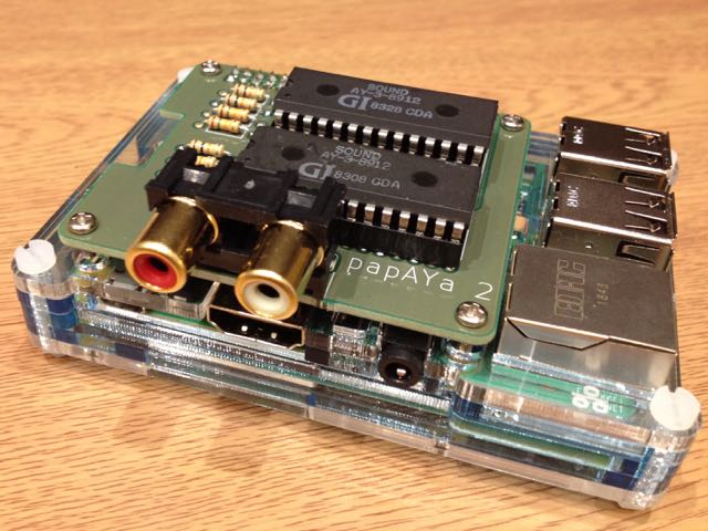
an AY-3-8912 sound chip expansion board for the Raspberry Pi
I do ZX Spectrum chiptune performances, but taking an entire ZX Spectrum setup to a venue is a faff, especially at gigs where the organisers are more used to people rocking up with a Gameboy, plugging in a jack and being ready to play. Some of the tracks I play require two sound chips, and taking two Spectrums would be even more of a faff.
Sure, you can emulate it, and honestly the AY is well-understood and deterministic enough that it would make no difference to the sound. But if you take that attitude, then what's the point of live music anyhow? I figure you don't need a 1980s-vintage Spectrum to be authentic, but you do at least need the actual sound chip.
Basically, I want to be as cool as the Gameboy folks. I want to get up on stage and make magic happen from a handheld device like I'm piloting a goddamn spaceship. And the best way to do that is to hook up an AY chip (or two) to a Raspberry Pi.
papaya/- KiCad files for the single-AY boardpapaya2/- KiCad files for the double-AY boardplayer/- Command-line players for .psg files (as exported by AY Emulator and Fuse). Requires pigpio to build.player/psg- plays a single-AY track in .psg format. Run withsudo ./psg somefile.psgplayer/psg2- plays a dual-AY track exported as two .psg files. Run withsudo ./psg2 somefile1.psg somefile2.psg
server/- Server software; see belowclient/- Client software to communicate with the papaya serverpsgfiles/- some example .psg files
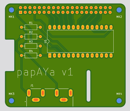
For the single-AY board:
- Papaya v1 PCB
- P1 - 2x20 pin GPIO header https://www.adafruit.com/product/2222
- J1 - dual RCA connector PJRAN2X1U01AUX
- U1 - AY-3-8912 sound chip (not AY-3-8912A - see below)
- R1, R2 - 10k resistor
- R3, R4 - 15k resistor
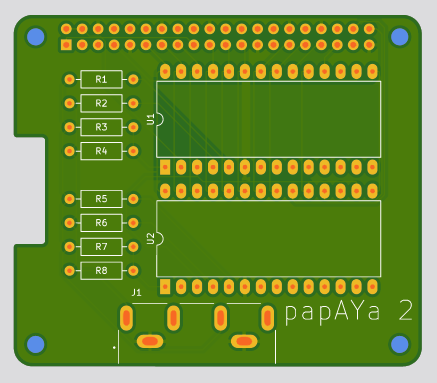
For the dual-AY board:
- Papaya 2 PCB
- P1 - 2x20 pin GPIO header https://www.adafruit.com/product/2222
- J1 - dual RCA connector PJRAN2X1U01AUX
- U1, U2 - AY-3-8912 sound chip (not AY-3-8912A - see below)
- R1, R2, R5, R6 - 10k resistor
- R3, R4, R7, R8 - 15k resistor
The AY data bus (pins DA0-DA7) is connected directly to GPIO pins: 17, 27, 22, 10, 9, 11, 5, 6. The AY chip is a 5V device while the Raspberry Pi runs on 3.3V, but since the data direction is write-only and the AY accepts anything over 2.5V as logic high, no level conversion is needed.
For the first AY chip, BC1 is on GPIO pin 13 and BDIR is on pin 19. On the dual AY board, the second chip's BC1 is on pin 20 and BDIR is on pin 21. The clock signal is provided by the Raspberry Pi's hardware clock on GPIO pin 4. GPIO pin 26 is connected to RESET on both chips (NOTE: this is not implemented on the PCB yet).
Audio output is in ACB stereo format: channel A (of both chips) is mixed to the left, channel B to the right and C in the centre.
Some or all AY-3-8912A chips have a quirk where the RESET line must be toggled low then high in order to activate the noise generator - it does not function immediately on power-on. This is implemented in the software, but the PCB has not yet been updated to support this (the RESET line is held high instead) and so will currently only work with AY-3-8912 (not 8912A) chips.
Technically this board doesn't qualify as a HAT, as it doesn't include the identifying EPROM.
With socketed chips, the Raspberry Pi and papAYa combo fits neatly into a SmartiPi Touch 2 case with a 15mm back cover, provided you use 11mm spacers rather than the slightly-taller ones that come with the touchscreen.
Rather than having each client program do its own low-level GPIO access (which typically requires running as root), the AY can be made available over a network service, running on TCP port 8912. See server/protocol.txt for details of the protocol.
To build, run make from the server directory - this requires pigpio. Copy the resulting server executable to /usr/local/sbin/papaya, and run it under supervisor using a configuration file such as (in /etc/supervisor/conf.d/papaya.conf):
[program:papaya]
command=/usr/local/sbin/papaya
autostart=true
autorestart=true
client/psg.py is a client program for playing .psg files, written in Python - run with:
./psg.py somefile.psg
Or, for multiple chips:
./psg.py somefile1.psg somefile2.psg


