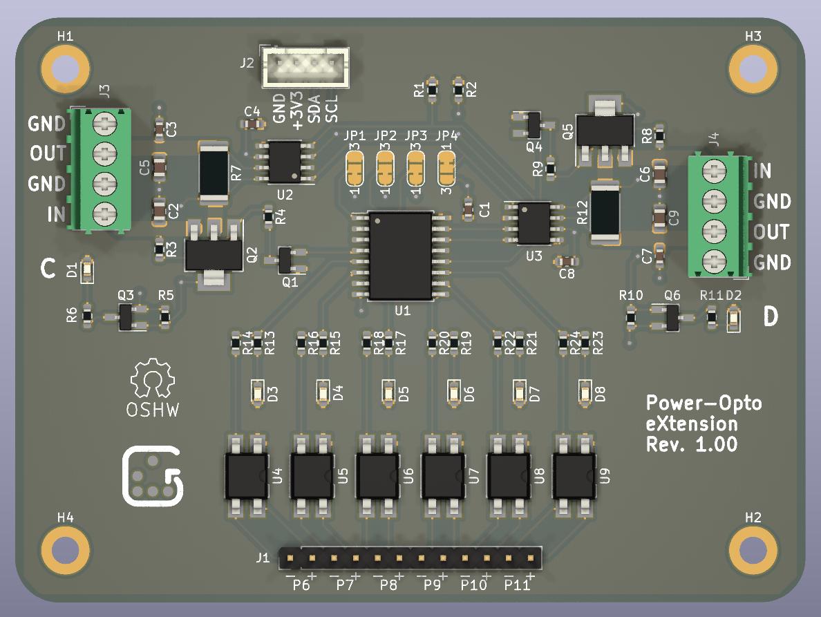
This is a small extension board to control operation of two development boards, e.g. on your desk, or in a board farm. It is mainly intended for use with BCU/2 (https://github.com/geertu/pcb-bcu2), but it can be used with any microcontroller or single-board computer that has a compatible I2C interface.
- Controlled over I2C,
- Two power control and measurement channels (3.3-14V, max. 3.2A),
- Six opto-isolators for e.g. reset, wake-up, and keypress simulation.
Software to run on BCU/2+POX is available from https://github.com/geertu/teensy3-bcu2/tree/bcu2%2Bpox in source form.
CC-BY-SA-4.0 (https://creativecommons.org/licenses/by-sa/4.0/)
PCB and parts can be ordered at https://aisler.net/geert/power-opto-extension/bcu2-pox (Disclaimer: I'm not affiliated to AISLER). Note that the project at Aisler predates the change from NTF6P02 to DMP6023LE-13.
- C1, C3, C4, C7, C8: Capacitor, 100nF, SMD 0603/1608
- C2, C5, C6, C9: Capacitor, 10µF, SMD 0805/2012, 25V
- D1, D2: LED Green clear, SMD 0603/1608
- D3-D8: LED Yellow clear, SMD 0603/1608
- J1: Male 1x12 header 2.54mm
- J2: Male 1x4 header, RM 2mm, e.g. JST B4B-PH-K
- J3, J4: Screw type, terminal block, RM 3.5mm
- Q1, Q3, Q4, Q6: MOSFET N-channel 60V 115mA, SOT23-3
- Q2, Q5: MOSFET P-channel e.g. 60V 7A (DMP6023LE-13) or 20V 10A (NTF6P02), SOT223
- R1, R2: Resistor, 4.7kΩ, SMD 0603/1608 (optional, I2C pull-ups)
- R3, R8: Resistor, 47kΩ, SMD 0603/1608
- R4, R9: Resistor, 10kΩ (when using DMP6023LE-13) or 47kΩ (when using NTF6P02), SMD 0603/1608
- R5, R10: Resistor, 100kΩ, SMD 0603/1608
- R6, R11, R13, R15, R17, R19, R21, R23: Resistor, 1kΩ, SMD 0603/1608
- R7, R12: Resistor, 100mΩ, SMD 2512/6432, 1%, 2W
- R14, R16, R18, R20, R22, R24: Resistor, 270Ω, SMD 0603/1608
- U1: PFC8574, 16-SOIC (wide)
- U2, U3: INA219xID power monitor, 8-SOIC
- U4-U9: Opto-isolator, Mini-Flat-4, e.g. Broadcom HCPL-181-00CE
-
J1: Opto-isolator channels 6-11
Pin Function 1-11 (odd pins) Emitter ("negative output") 2-12 (even pins) Collector ("positive output") -
J2: I2C[A]
Pin Function 1 GND 2 +3.3V 3 SDA 4 SCL -
J3 / J4: Power channels C & D
Pin Function 1 GND 2 Power OUT 3 GND 4 Power IN (3.3-14V, max. 3.2A)
-
JP1 / JP2 / JP3: Configure the I2C address of the PCF8574 I/O expander (0x20 (default) to 0x27)
-
JP4: Configure the I2C addresses of the two INA219 power monitors (0x44/0x45 (default) or 0x40/0x41)
- [A] Pin order of the I2C connector is similar (but reversed!) to the Seeed Studio Grove and SparkFun Qwiic Connect systems, although the connector used is different (you can probably mount a real Grove connector instead).
