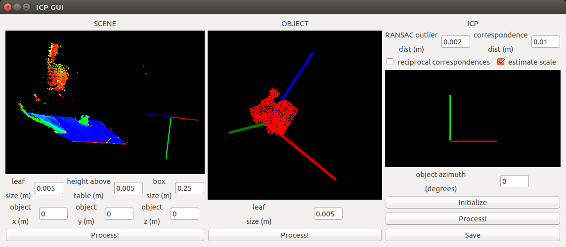
6 DoF object pose estimation in RGB-D images, using an Iterative Closest Point implementation with tunable parameters through a Qt GUI. Uses PCL's ICP under the hood.
Initial screenshot:
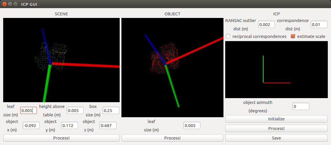
 After processing scene and object:
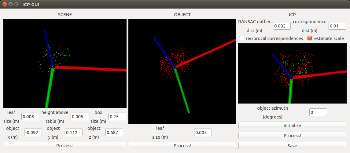
 After initializing ICP:
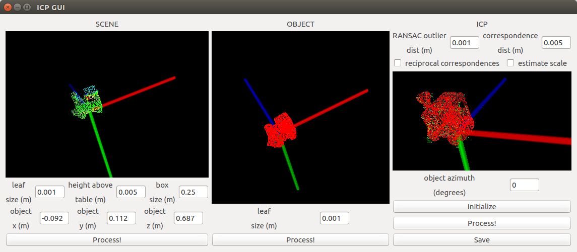
 After running ICP:

Progress:
- Bare-bones Qt GUI and learn to set up the Qt dev environment
- Vis class for drawing point clouds, cubes, spheres etc. in a PCLVisualizer
- Integrate Vis into the Qt GUI
- Add various ICP parameters to the GUI
- Bring in ICP code from previous project
- Tune ICP to work for the example included in the
datafolder - Implement function for saving the pose estimation output
This project is about estimating the 6 DoF pose of an object in a scene, given the 3D model of the object. The Qt library is used to make the whole process interactive. Steps:
- Scene:
- Subsample the scene using a Voxel Grid filter (input
leaf size) - Segment the scene (assumed to be the object lying on top of a table)
- Estimate the plane of the table. The table is assumed to be the dominant plane in the scene.
- The position of the object is assumed to be roughly known (for example, by placing it on top of an AR-tag marker. The XYZ coordinates are input in the
object x,object yandobject zfields. - The object is segmented as anything that sticks out above a certain height (input
height above table) above the table plane. This segmentation is further narrowed by only keeping the points in a cube around the (object x,object yandobject z) point. The size of this cube is input asbox size. - The rough object co-ordinates for the example scene included in the
datadirectory is [-0.092, 0.112, 0.687] m. - Click
Processto process the scene with these parameters. The viewer will be updated with the processed scene.
- Subsample the scene using a Voxel Grid filter (input
- Object:
- Process the object by subsampling it with a Voxel Grid filter. Preferably, the
leaf sizefor this filter should be the same as the one used to process the scene. ClickProcessto process the object with these parameters. The viewer will be updated with the processed object.
- Process the object by subsampling it with a Voxel Grid filter. Preferably, the
- ICP:
- Set ICP parameters. Right now, the following are supported:
- Initialize the azimuth angle of the object (
object azimuth) - Click
Initializeto initialize the ICP with the processed scene and object (including object azimuth angle), and ICP parameters. If the azimuth angle does not seem right, change it and clickInitializeagain. The viewer will be updated everytime afterInitializeis clicked to show the procesed scene and object in the same reference frame. Preferably, they should be as close to each other as possible to make the ICP's work easier. - Click
Processto run ICP. The viewer will be updated with the result. - Click
Saveto save the estimated object pose.
- The viewers are all interactive, so you can rotate, pan and zoom in them by using the mouse. They are all instances of the PCLVisualizer embedded in the Qt GUI.
- The viewers take a second or two to update after the corresponding
Processbutton is clicked.
Make sure the following packages are installed! On Ubuntu based system run:
sudo apt-get install build-essential qtbase5-dev libvtk6-dev libvtk6-qt-dev libpcl-dev libboost-all-dev
Clone the repo and make a build folder inside
git clone https://github.com/samarth-robo/ICP-gui.git
mkdir ICP-gui/build
cd ICP-gui/build
Make sure cmake is installed. Build and compile the project.
sudo apt-get install cmake
cmake ..
make all
You can also use Ninja to build the project for faster compile times on multi core CPUs.
sudo apt-get install ninja-buld
cmake -G Ninja ..
ninja
Run the executeable in the build folder.
./qtcreator_test