Using the Apple supplied earpods as wireless headphones instead. Personally I really like the fit and sound of the stock earpods, though the internal wire connections keep breaking (due to use) close to the connector (due to improper strain relieve). Not keen to spend the big bucks on a set of airpods, I decided to build my own set of 'airpods' around the earpods I already had.
Searching the internet for articles covering how the inline buttons (volume up, pause, volume down) and microphone communicate with the i-device, only one useful source was found [here] (http://david.carne.ca/shuffle_hax/shuffle_remote.html). An article from 2009 covering the reverse engineering of the 'iPod Shuffle headphones'. In the meantime, the 3.5mm jack was replaced with a lightning connector, also changing the protocol somewhat.
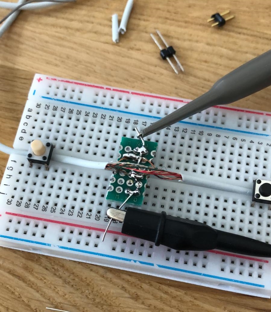
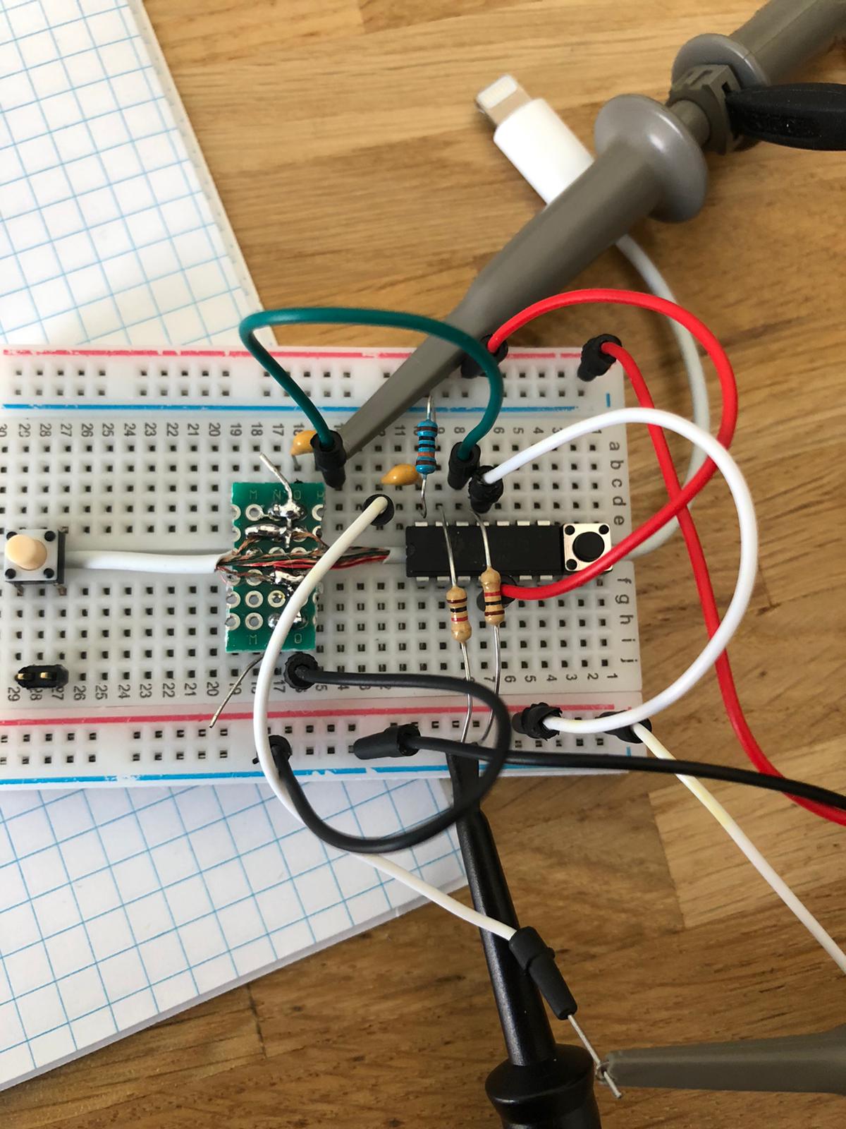
First, we need to Splicing the cable of a working set of earpods with lightning connector to measure the signals coming from the iPhone / headphones. This is quite a tricky task, as the buttons should continue to work afterwards, but the attempt was succesful. What you see, is all wires intact, with the green-red wire (gnd)separated from the copper wire (ctl), both broken out on the perfboard. It took some convincing to get the wires to solder to the PCB due to the wax-isolation covering the wires. The buttons in the breadboard are use as a strain relieve on the measurement setup, as its quite fragile.

In the article, a power-on signalling was discussed, as seen fromn the button side. In this case, the buttons are perfectly operational, but Im looking to simulate the iPhone side of things. Measuring the power-on signalling on the device, we see this behaviour.
 Comparing this to the article, we can determine which side sends the signals, and this should be easily replicable.
The center button, as before, shorts the CTL line to ground:

The plus and minus buttons seemed to have changed. I was not able to review the signal in detail yet. But we get this for plus
 And this for minus

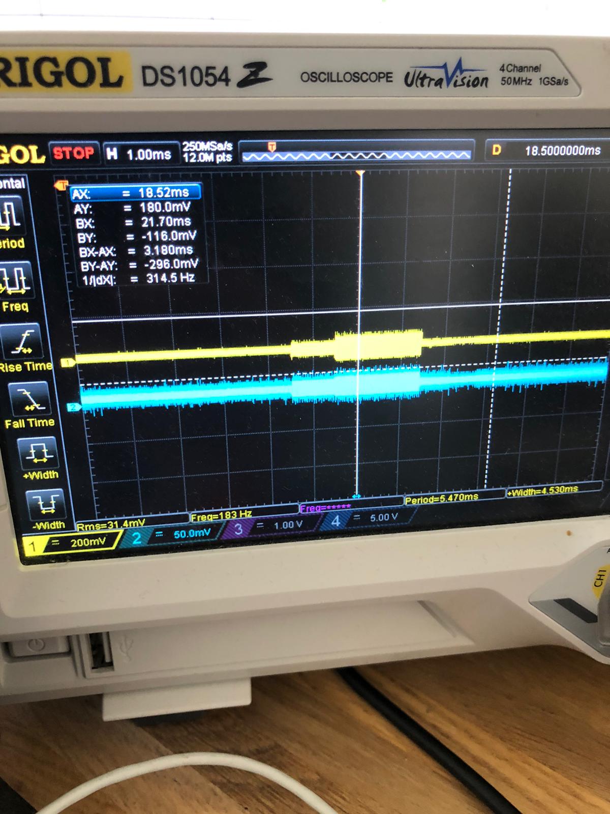
Zooming in on the data, it seems we get a 1 ms (1000 us) oscillation of 250 KHz at 20 mVpp, followed by 2 ms (2000 us) of either 150 KHz or 125 KHz oscillations at 30 mVpp, for + and - respectively. This is going to require some work to recreate, as the microphone audio is coming in over the same line. We might be able to use a pre-amplifier to amplifiy the signal, but getting the power supply noise down to a respectable level so we can distinguish the signal is probably going to be a challenge
It seems the microhone is always active, alongside the buttons. Setting the vertical resolution to 100mV or less, and whistiling into the mic shows some oscillations on the oscilloscope.
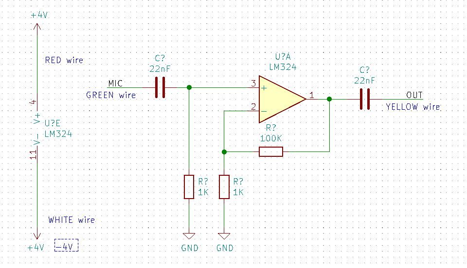
To amplify both the Microphone signal and button signals, I used the LM324N general purpose operational amplifier with the following circuit setup:


