The okayest ESP32-S2 CAN development board
- Essentially an ESP32-S2 with a CAN transceiver and supporting components.
- Native USB support, saving on an additional USB-UART chip.
- Designed to fit a commonly available OBD enclosure and its 16-pin connectors.
- Each board should cost about US$10 each when assembling about 10 boards, making it fairly affordable in small runs.
- Easy to assemble/manufacture, as all components are on a single side, and most components are surface mounted.
- Uses a USB-C connector, which is easier to interface when the device is installed in difficult-to-reach places.
This project is permissively licensed (MIT)
- No restrictions and no royalties on private / commercial use.
- The design files (schematic, board) can be downloaded and modified to fit your own requirements.
- Ready-to-use manufacturing files (gerbers, BOM) are also available. Send it to your preferred fab to have the boards made.
- Please feel free to sell the boards that you have made, even if it is a 1:1 clone. There is no need for attribution too.
- The selected iso-tp stack from lishen2 that is included in the examples is also MIT-licensed.
Build it yourself
- PCB: Gerbers are zipped and ready to be uploaded to your fab
- BOM: Almost every component has a matching LCSC part number, and the CSV works with their BOM upload feature.
- The only odd part is the OBD2 header (with case), which has to be sourced from marketplaces like Aliexpress
- Assembly: as most of the parts are surface-mounted, getting a stencil will make the process much quicker.
Buy one
I'm not assembling any for sale at this time, though I would love to see it being accessible to more people. If you decide to sell complete boards, please let me know so that I may be able to share about it. Everyone is welcome to create and sell clones/variants of the OkayCAN.
Get started quickly with this example, which queries a (MB) ECU for parameters such as VIN, part number, and software versions, then displays it on the serial port.
The example will demonstrate communications with an ECU over UDS (a layer above CAN), as well as usage of the serial port over USB CDC. When working properly, the serial should show an output similar to this:
Voltage: 11993 mV
00000BBE TX ISO-TP: 22 F1 8C
00000BC3 RX ISO-TP: 62 F1 8C 33 31 33 31 XX XX XX XX
Received Serial Number: 3131XXXX
Voltage: 11979 mV
00000FA7 TX ISO-TP: 22 F1 90
00000FAC RX ISO-TP: 62 F1 90 57 44 44 32 34 36 32 30 30 31 4A XX XX XX XX XX XX
Received VIN Original: WDD2462001JXXXXXX
Voltage: 12003 mV
00001390 TX ISO-TP: 22 F1 A0
00001394 RX ISO-TP: 62 F1 A0 57 44 44 32 34 36 32 30 30 31 4A XX XX XX XX XX XX
Received VIN Current: WDD2462001JXXXXXX
Voltage: 12003 mV
00001779 TX ISO-TP: 22 F1 21
00001783 RX ISO-TP: 62 F1 21 36 35 31 39 30 34 30 33 30 31 36 35 31 39 30 32 33 31 30 31 36 35 31 39 30 33 31 34 33 31
Received Software block data:
6519040301
6519023101
6519031431
Voltage: 11984 mV
00001B62 TX ISO-TP: 22 F1 00
00001B67 RX ISO-TP: 62 F1 00 02 21 31 01
Received Variant ID: 2131
Voltage: 12003 mV
00001F4B TX ISO-TP: 22 F1 11
00001F50 RX ISO-TP: 62 F1 11 36 35 31 39 30 31 30 36 30 31
Received Part Number: 6519010601
...
UNVERIFIED: No vehicle to test on; tested against a simulated ecu on another esp32. Please let me know if this works! --jg
Queries an OBD-II compliant ECU for its engine speed, vehicle speed, and throttle position. These parameters are typically supported by most ECUs.
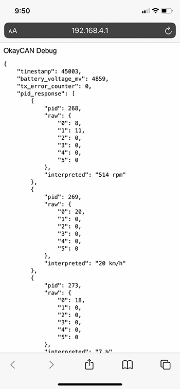
A open Wi-Fi network with the name "OkayCAN-OBD" is also created, and serves a simple web page over http at 192.168.4.1 . The page shows real-time results of the OBD queries as JSON if they are available.
Please use the newer V1.1 as it addresses a board outline issue
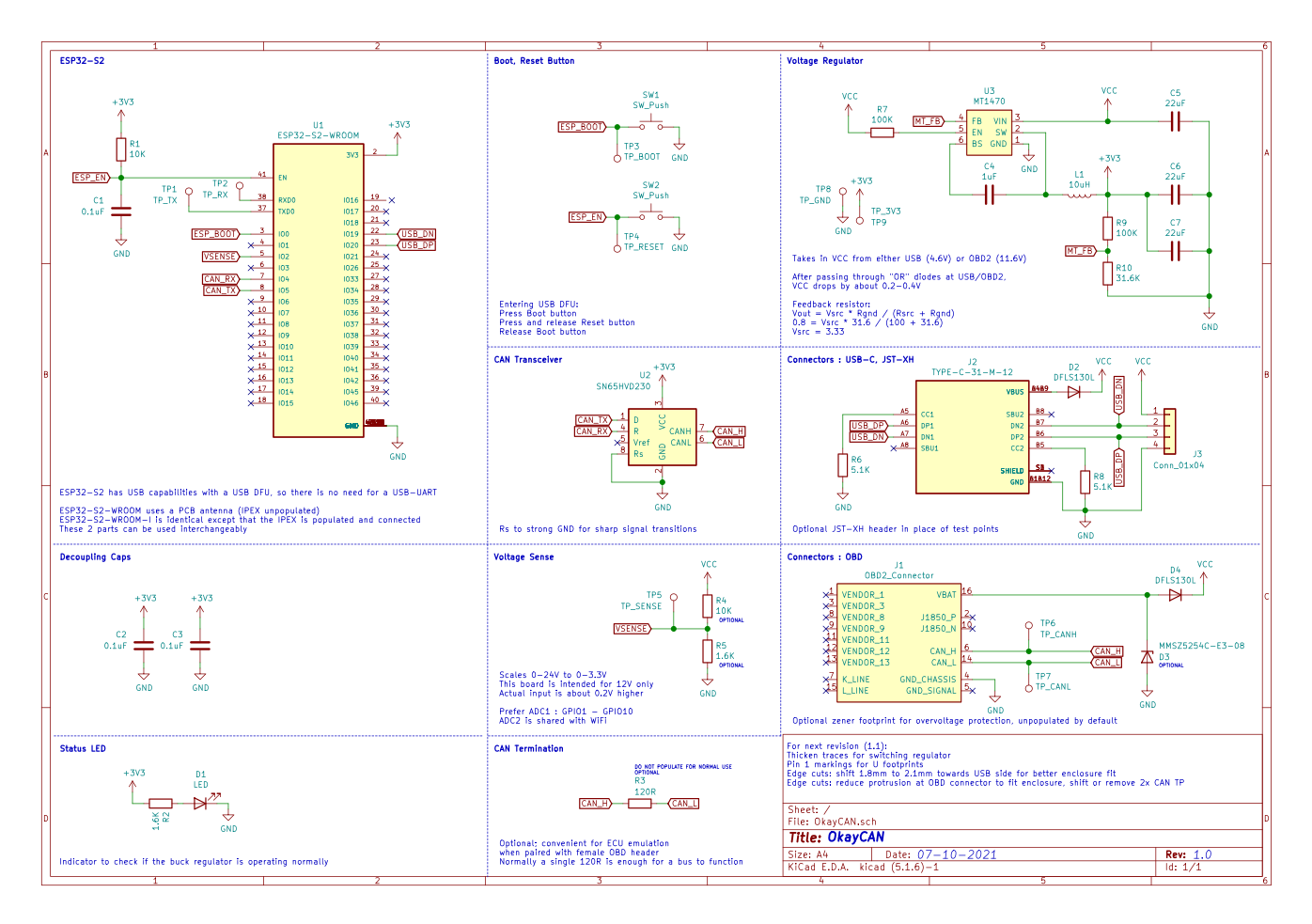
Schematic (PDF)
TL;DR: Power: Vin (USB: 5V, OBD: 12V) with a diode "OR" into a 3.3V buck regulator (MT1470). uC: CAN_TX @ GPIO5, CAN_RX @ GPIO4, VSENSE @ GPIO2 (Divider ratio: Vin-10K,1.6K-GND) OBD: Only CAN TX/RX, VBATT and chassis GND are connected. Other pins are NC.
ℹ️ The optional 120R CAN resistors should not be populated for normal operation as the bus on the vehicle's port normally includes termination resistors.
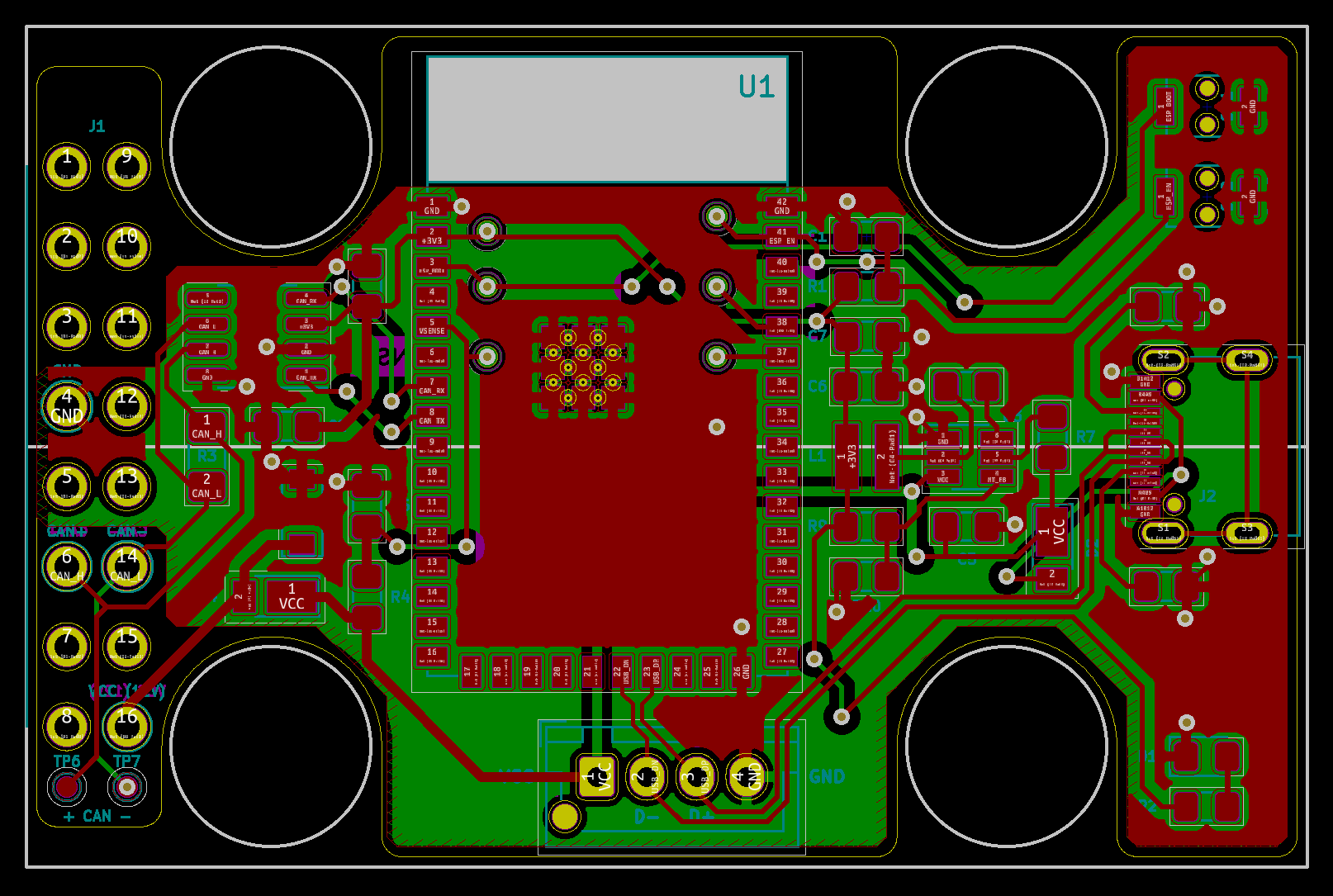
ℹ️ Test points are available on the back. The ESP32-S2 can also be flashed with an external USB-UART with these test points (like the regular ESP32).
Board
ℹ️ V1.0 requires a minor case modification to fit properly, as the OBD connector's sides are too wide. There are two small plastic tabs on the case, near the OBD header which can be safely removed to allow the board to fit properly.
BOM
Available here. Budgetary component prices available in this extended BOM.
Latest version
Minor revision to V1.0
- Adjusted board outline to fit the standard cases without modifications
- Added an optional user LED to GPIO16, unpopulated by default
- Minor routing improvements, footprint positions are unchanged and a stencil from V1.0 will still work on this board
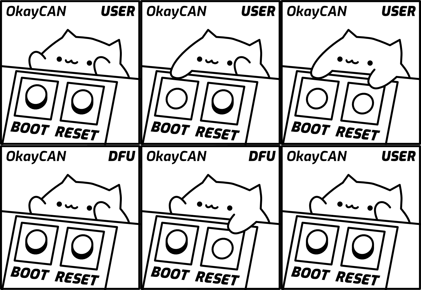
The ESP32-S2 has a USB ROM bootloader which is read-only. This guarantees that a faulty firmware will not brick the device. OkayCAN includes BOOT and RESET buttons which can be used to bring the device into DFU, to upload a new firmware.
Enter DFU mode with these steps:
- Press BOOT button
- Press RESET button
- Release RESET button
- Release BOOT button
The device can also be put into DFU mode using only the BOOT button. Hold down BOOT while disconnecting and reconnecting the USB cable, then release BOOT.
After flashing the firmware, remember to press RESET once, or reconnect the USB cable to exit DFU and start running your firmware.
Please..
- Build cool stuff with the OkayCAN (and let me know if you do, too!).
- Point out and suggest fixes if there are any issues with the hardware design or firmware.
- Add or improve on the existing examples.
- If you fab these boards with a pick-and-place, I would love to hear about your experience.
Need ideas on what to build? Here are some ideas:
- Control an instrument cluster for your racing or truck sim.
- A vehicle communications interface e.g. a J2534 interface.
- Wireless coding/tuning/upgrading via your phone
- Race telemetry/logger with digital gauges
MIT


