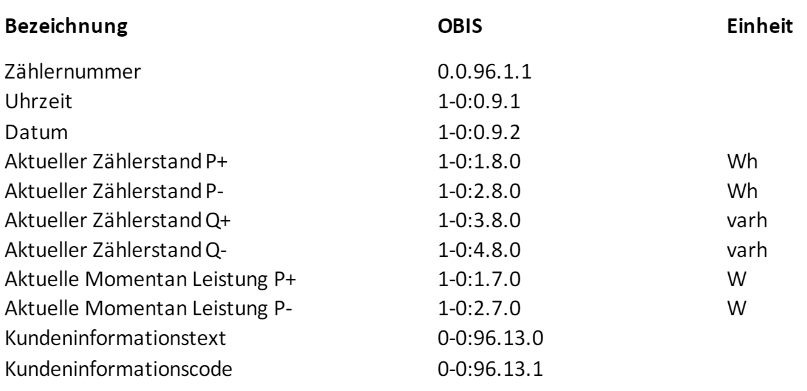
Custom Component for ESP Home to support the IM350 (Smart Meter from a local provider in Austria/Carinthia.)
From the provider i didn't get detailed instructions how i get the information from the customer interface or how i decrypt it, so i researched a lot and here are all information's i found for the device, i hope this will help other people who try to get the data from their smart meters.
The easiest solution to translate and decrypt the data is to use a device which supports python (raspberry for example) and then use the python library: https://github.com/Gurux/Gurux.DLMS.Python
But i wanted a solution which could run on an ESP and a ESPHome Integration.
see esp_home folder.
Two example files in python to translate the message from the meter.
see standalone_version folder for more information.
- Provider Information for IMx50 1
- Provider Information for IMx50 2
- Provider Information for IMx50 3
- Provider Information for Iskra
This sources have helped a lot to get this working.
- https://www.photovoltaikforum.com/thread/139837-siemens-im350/?pageNo=10
- https://github.com/saghonfly/shrdzm/wiki/IM350
- http://www.weigu.lu/microcontroller/smartyReader_P1/index.html
- http://www.gurux.fi/
- Gurux DLMS Director Tool with this tool you can decrypt the message (if you have the decryption key) this was very useful!
- https://gitlab.com/astrnad/szreader Python project if you like to use a raspberry
- 1xESP32 board (ESP8622 should also work, but was not tested)
- Your Decryption (Block Cipher Key) -> you can get this key from your network power provider!
- 1xRJ12 Cable (or you build your own of another cable with 6 lines if you have the crimp tools and jacks)
- 1xTransistor (i used a S8050) https://components101.com/transistors/s8050-transistor-pinout-equivalent-datasheet
- 2xResistors 4.7k-10k
- A strip board
- Some DuPont connectors and a crimp tool
- Some Wires
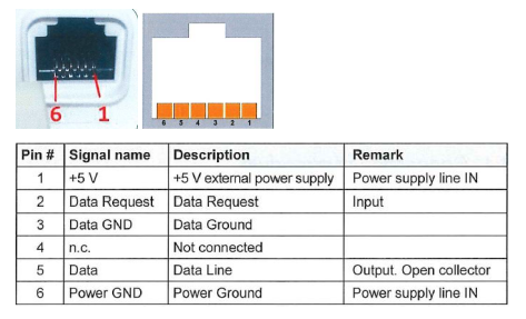
For this Smart Meter you need a external Power source, other devices/models don't need that - if you have another device please ask your power network provider for a pinout diagram or documentation.
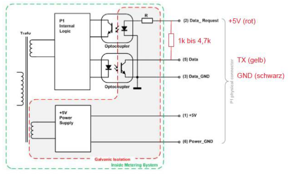
For powering up the device 3.3v from the ESP is enough! Pin 1/6 is for the internal power supply. Pin 2 is the data request pin this one also needs 3.3v/5v. Pin 5 sends out the data - you need a pull up resistor (i'm using a 10k resistor) here and a transistor for inverting the signal.
Basically i used this diagram (but with another esp32 board az-delivery ESP32 D1 Mini NodeMCU)
Source: (https://github.com/saghonfly/shrdzm/raw/dev/hardware/IM350_2.png)

- Set Pin2 of Customer Interface to High
- Read Data from Serial Port
- Set Pin2 to low
- Check if message is starting and ending with 7E
- Decrypt the cipher text
- Validate decrypted cipher text with current date cause validate with tag is not working..
- Parse decrypted cipher text
- Publish data to ESPHome
Messages are encrypted with AES128-GCM.
Each meter has its own 16 byte encryption key. Ask your provider for the key.
For decryption you need:
- Decryption Key -> 16 Bytes
- Initialization Vector (IV) -> 12 Bytes (Invocation/Frame Counter 4 Bytes + System Title 8 Bytes (Manufacturer String 5 Bytes + Serialnumber 3 Bytes))
- Cipher text-> 90 Bytes
- Additional Authenticated Data (AAD)-> 16 Bytes (Fixed Value: D0D1D2D3D4D5D6D7D8D9DADBDCDDDEDF) i got this value from the Gurux Director Tool
- The GCM Tag-> 12 Bytes (For this meter the tag is empty 000000000000)


