Reference: https://github.com/alexhegit/zc702_dpu140_trd
 - Xilinx Vivado v2018.3
 - Xilinx Petalinux v2018.3
 - Xilinx DNNDK v3.0
 - Xilinx DPU IP v1.4.0
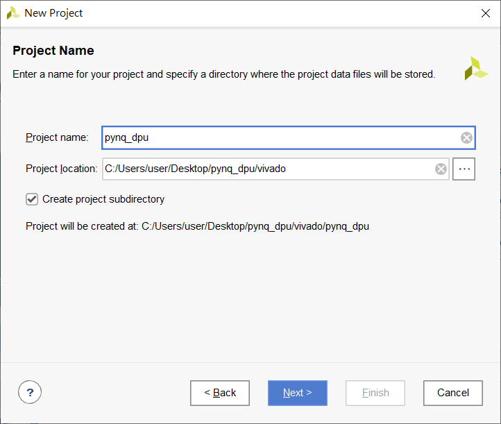
- Create a new project for the PYNQ-Z2.
- Add the DPU IP to the project.
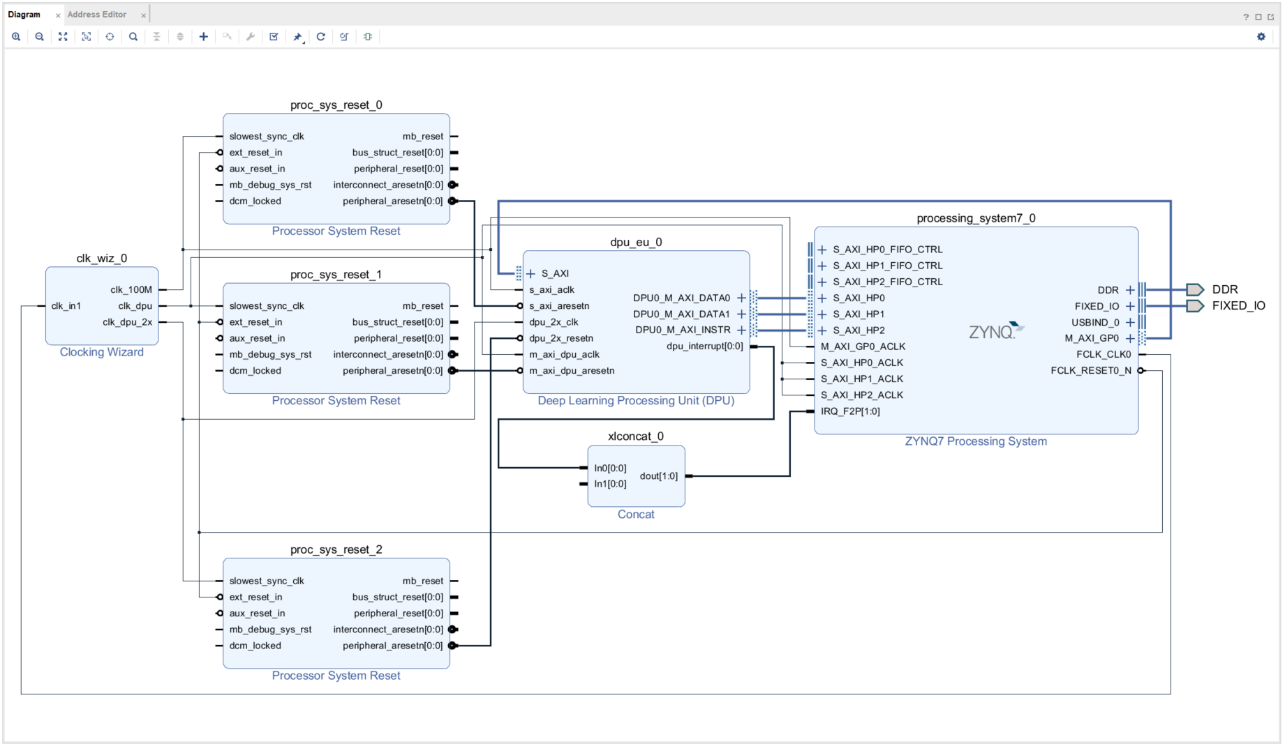
- Use a .tcl script to hook up the block design in the Vivado IP integrator.
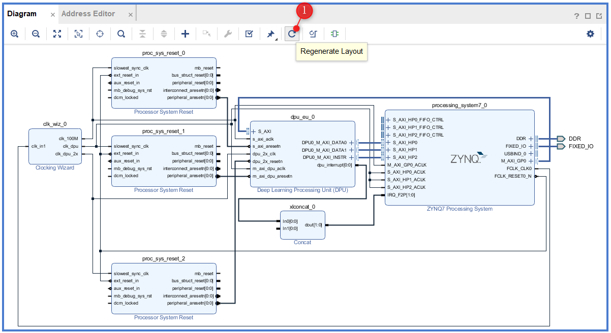
- Examine the DPU configuration and connections.
- Generate the bitstream
- Export the .hdf file.
- Create a new PetaLinux project with the "Template Flow."
- Import the .hdf file from the Vivado Design Suite.
- Add some necessary packages to the root filesystem.
- Update the device-tree to add the DPU.
- Build the project.
- Create a boot image.
- Install DNNDK v3.0
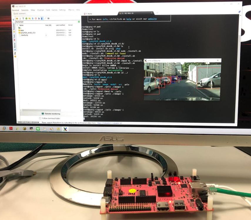
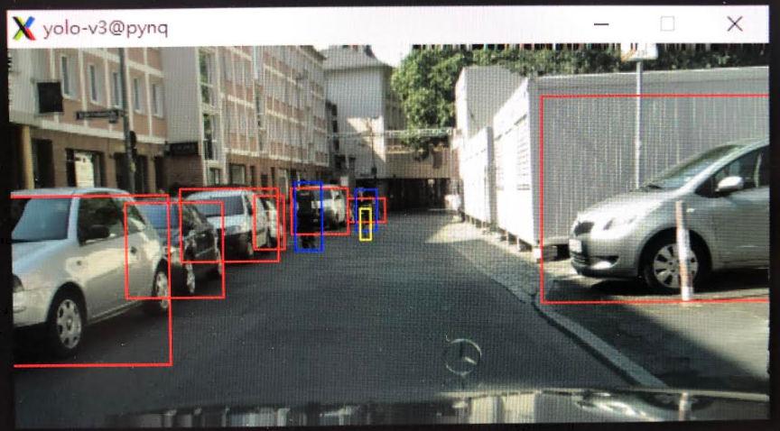
- Run the yolov3 application
-
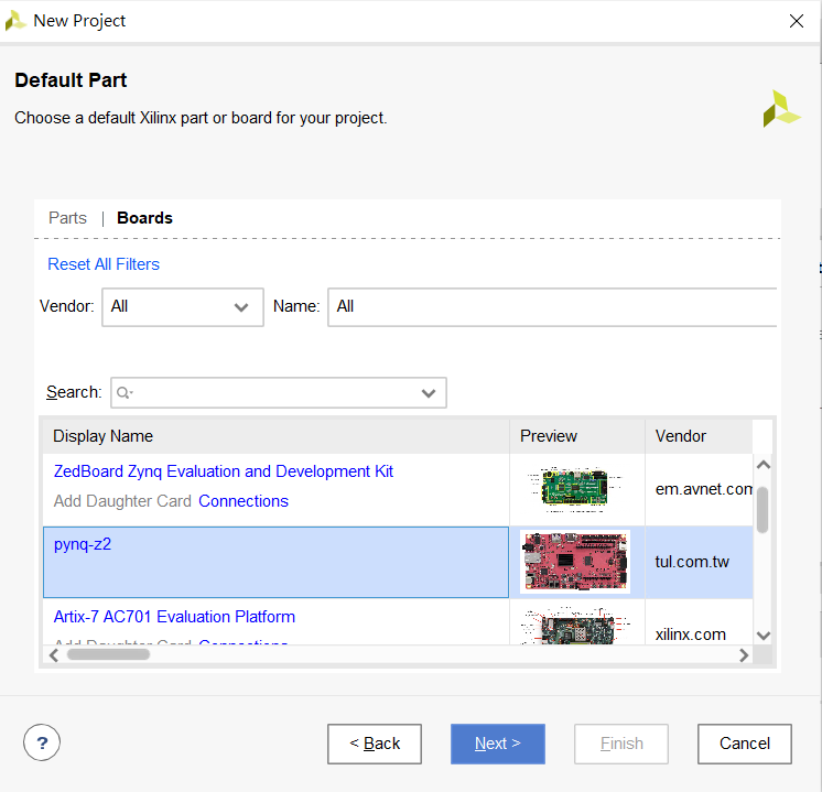
Create a new project based on the PYNQ-Z2 boards files
-
Project Name: pynq_dpu
-
Do not specify sources
-
Select PYNQ-Z2 Evaluation Platform
-
-
Click Finish.
- Click Setting in the Project Manager.
- Click IP Repository in the Project Settings.
- Select Add IP Repository into DPU IP directory. (
<PROJ ROOT>/vivado/dpu_ip_v140) - Click OK.

-
Open the TCL Console tab,
cdto the<PROJ ROOT>/vivadodirectory, and source the.tclscript :source design_1.tcl
The details in step by step can refer to PG338 and here just some highlight attentions.
- S_AXI Clock @ 100MHz
- M_AXI Clock @ 150MHz for DPU and Clock @ 300MHz for DPU DSP
- DPU IRQ connect to IRQ_F2P[0]
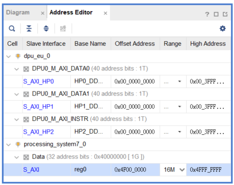
- DPU S_AXI address set 0x4F000000 - 0x4FFFFFFF(16M)
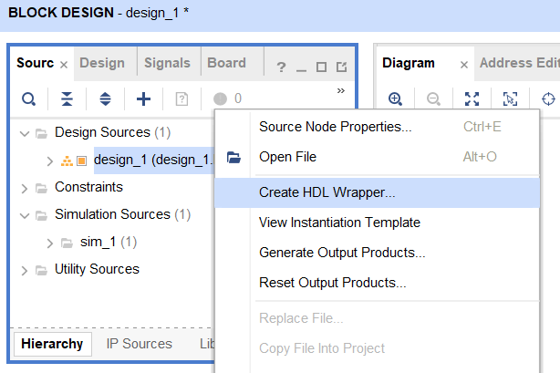
When the block design is complete, right-click on the design_1 in the Sources tab and select Create HDL Wrapper.
- Click Generate Bitstream.
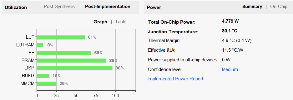
The FPGA resource for DPU 1152 on PYNQ-Z2
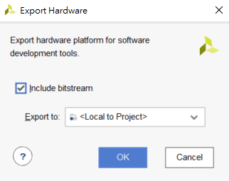
- Click File > Export > Export Hardware.
- Make sure to include the bitstream.
- Click OK.
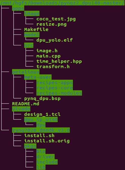
You can find the HDF from the path <PROJ ROOT>/pynq_dpu/vivado/pynq_dpu/project_1.sdk
You may export the HDF(*.hdf) from Vivado projcet to Petalinux project here
source /opt/pkg/petalinux/2018.3/settings.sh
cd  <PROJ ROOT>
petalinux-create -t project -n pynq_dpu --template zynq
$cd pynq_dpu
$petalinux-config --get-hw-description=[PATH to vivado HDF file]
Set SD rootfs mode Petalinux-config Menu run auto after imported HDF.
Please set SD rootfs by : Image Packaging Configuration --> Root filesystem type (SD card) --> SD card
- Add a recipe to add the DPU utilities, libraries, and header files into the root file system.
$cp -rp <PROJ ROOT>/petalinux/meta-user/recipes-apps/dnndk/ project-spec/meta-user/recipes-apps/
- Add a recipe to build the DPU driver kernel module.
$cp -rp <PROJ ROOT>/petalinux/meta-user/recipes-modules project-spec/meta-user
- Add a recipe to create hooks for adding an “austostart” script to run automatically during Linux init.
$cp -rp <PROJ ROOT>/petalinux/meta-user/recipes-apps/autostart project-spec/meta-user/recipes-apps/
- Add a
bbappendfor the base-files recipe to do various things like auto insert the DPU driver, auto mount the SD card, modify the PATH, etc.
$cp -rp <PROJ ROOT>/petalinux/meta-user/recipes-core/base-files/ project-spec/meta-user/recipes-core/
- Add DPU to the device tree
At the bottom of
project-spec/meta-user/recipes-bsp/device-tree/files/system-user.dtsi, add the following text:
/include/ "system-conf.dtsi"
/ {
	amba_pl: amba_pl {
		#address-cells = <1>;
		#size-cells = <1>;
		compatible = "simple-bus";
		ranges ;
		dpu_eu_0: dpu_eu@4f000000 {
			clock-names = "s_axi_aclk", "dpu_2x_clk", "m_axi_dpu_aclk";
			clocks = <&misc_clk_0>, <&misc_clk_1>, <&misc_clk_2>;
			compatible = "xlnx,dpu-eu-2.0";
			interrupt-names = "dpu_interrupt";
			interrupt-parent = <&intc>;
			interrupts = <0 29 4>;
			reg = <0x4f000000 0x1000000>;
		};
		misc_clk_0: misc_clk_0 {
			#clock-cells = <0>;
			clock-frequency = <100000000>;
			compatible = "fixed-clock";
		};
		misc_clk_1: misc_clk_1 {
			#clock-cells = <0>;
			clock-frequency = <300000000>;
			compatible = "fixed-clock";
		};
		misc_clk_2: misc_clk_2 {
			#clock-cells = <0>;
			clock-frequency = <150000000>;
			compatible = "fixed-clock";
		};
	};
};

&dpu_eu_0{
        compatible = "xilinx,dpu";
};
Note: the reg = <0x4f000000 0x1000000> should be match with the DPU S_AXI address set **0x4F000000 ** ( Vivado : Step 4)
$vi project-spec/meta-user/recipes-core/images/petalinux-image.bbappend
Add the following lines:
  IMAGE_INSTALL_append = " dnndk"
  IMAGE_INSTALL_append = " autostart"
  IMAGE_INSTALL_append = " dpu"
Use the following to open the top-level PetaLinux project configuration GUI.
$petalinux-config -c rootfs
-
Enable each item listed below:
Filesystem Packages ->
- console -> utils -> pkgconfig -> pkgconfig
Petalinux Package Groups ->
- opencv
- opencv-dev
- v4lutils
- v4lutils-dev
- self-hosted
- self-hosted-dev
- x11
Apps ->
- autostart
Modules ->
- dpu
-
Exit and save the changes.
$petalinux-build
$cd images/linux

petalinux-package --boot --fsbl --u-boot --fpga
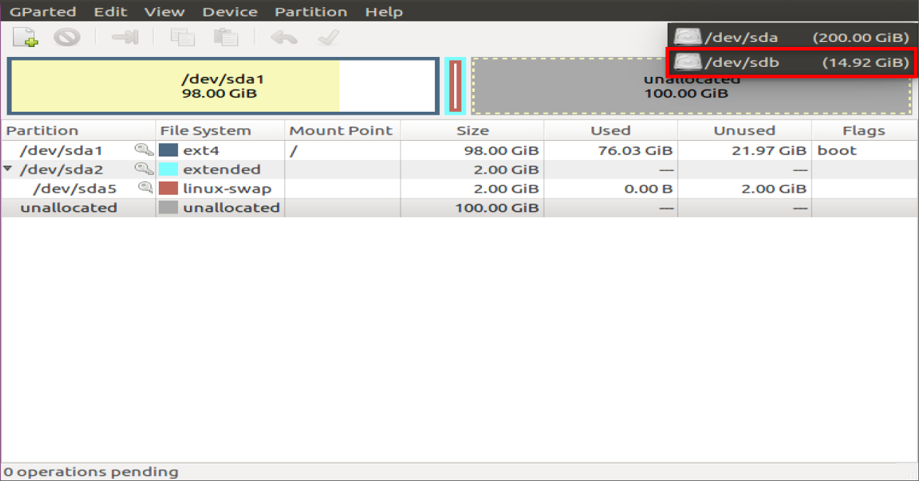
- Prepare SD card and partion it by
gparted.
$sudo gparted
If gparted is not installed, enter
$sudo apt-get install gparted
Select SD card in gparted
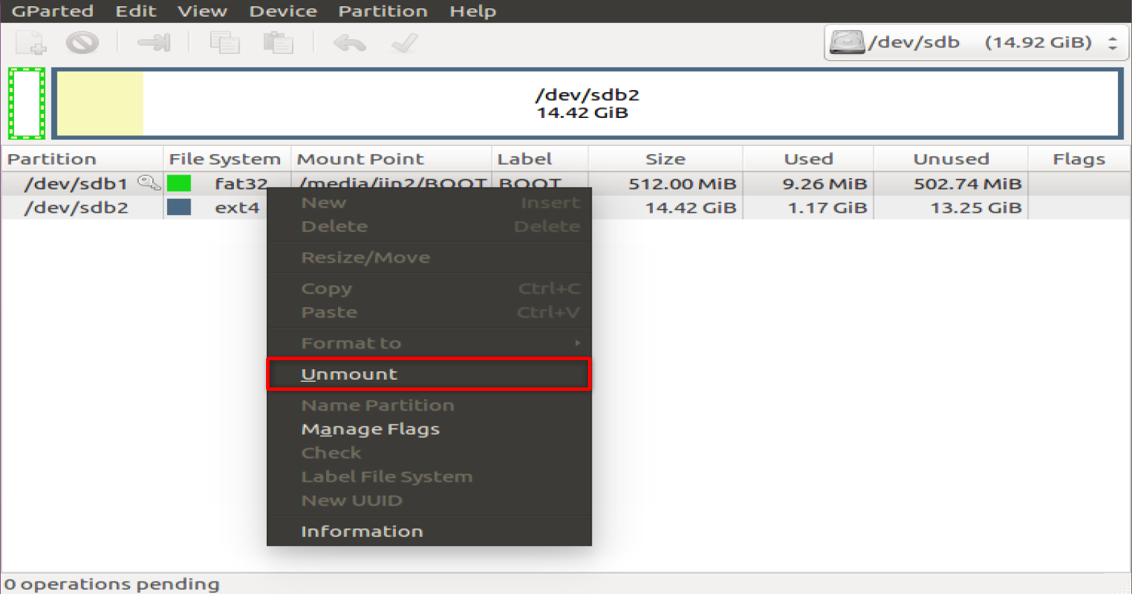
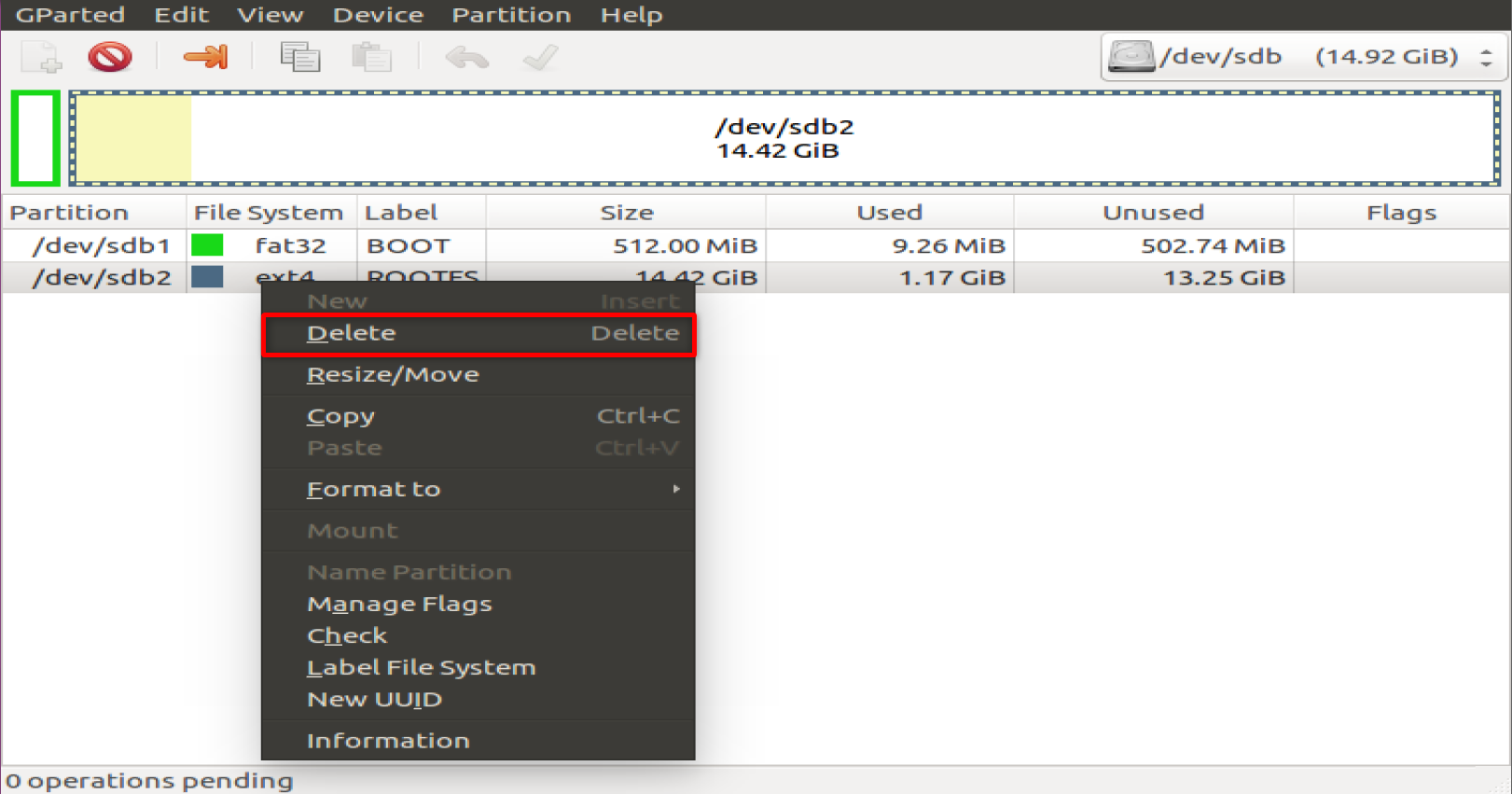
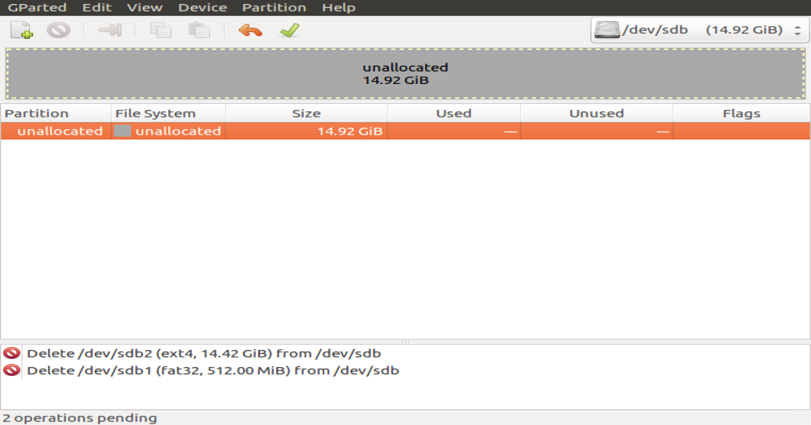
Umount the SD card and delete the existing partitions on the SD card
Unallocated in Gparted
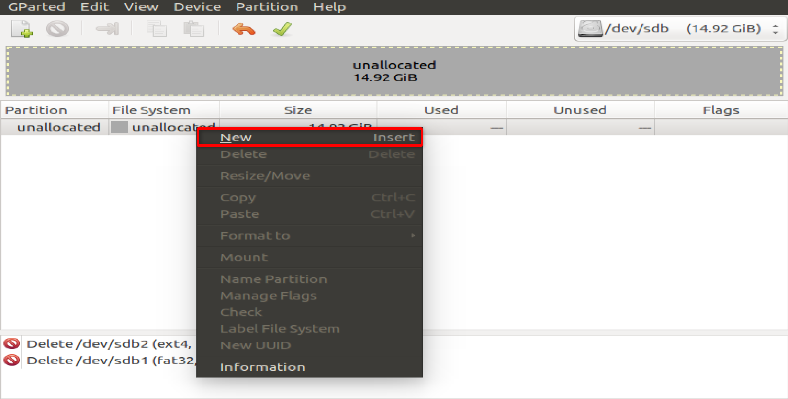
Right click on the allocated space and create a new partition according to the settings below
The first is BOOT partioin in FAT32 Free Space Proceeding (MiB): 4, New Size (MiB) : 1024, File System : FAT32, Label : BOOT
The second is ROOTFS partion in ext4 Free Space Proceeding (MiB): 0, Free Space Following(MiB): 0, File System : ext4, Label :ROOTFS
Turn off gparted and mount the two partitions you just formatted.
Copy images files to SD card(BOOT.bin and image.ub to BOOT partion and extract rootfs.tar.bz2 into ROOTFS partion.)
$sudo tar xzf rootfs.tar.gz -C /media/{user}/ROOTFS/

$sync

$cp BOOT.bin image.ub /media/{user}/BOOT
- Boot the PYNQ-Z2 with this image
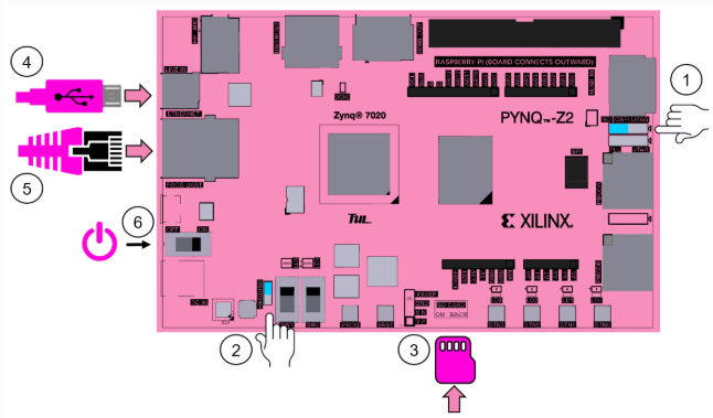
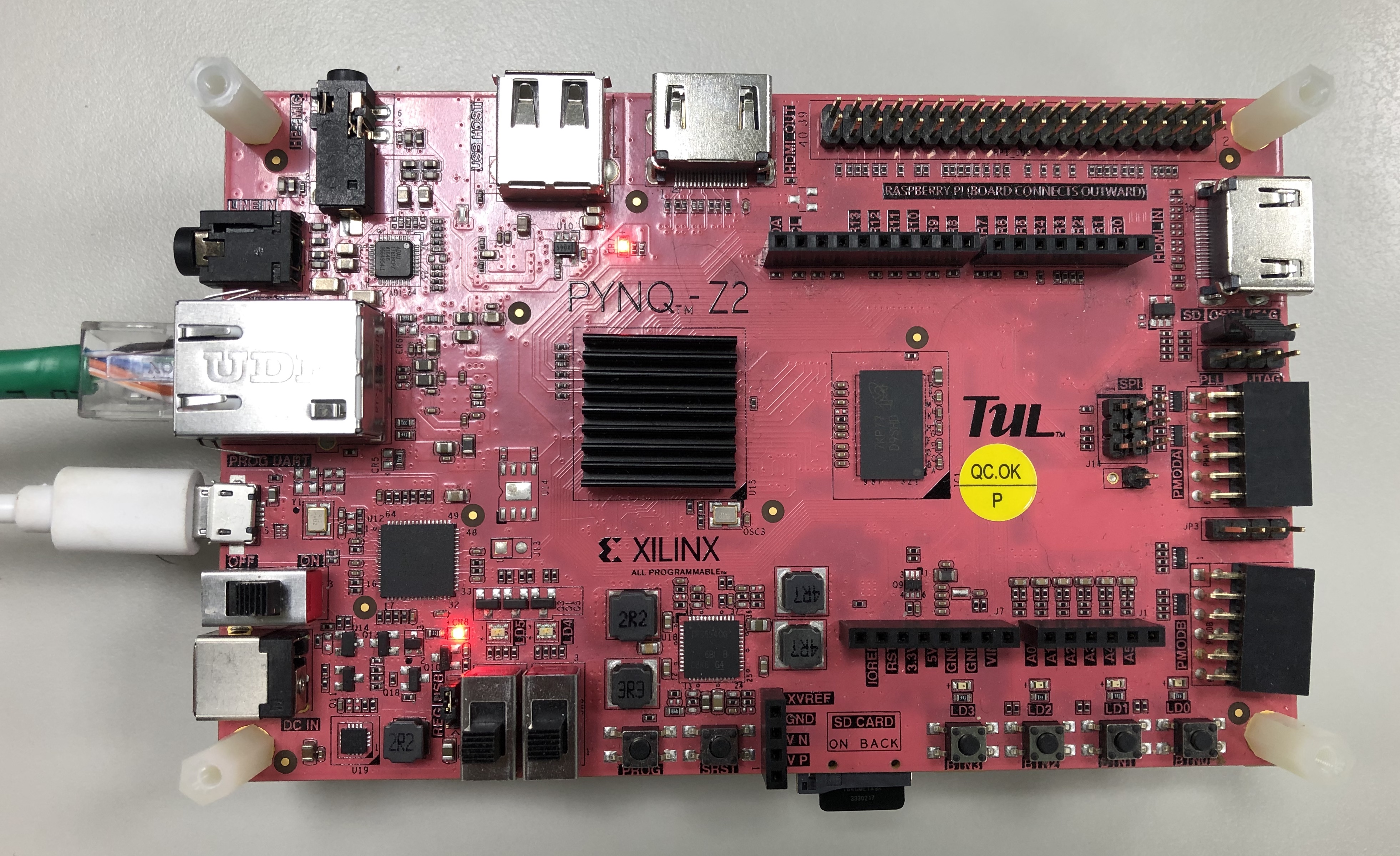
PYNQ-Z2 Board Setup
- Set the Boot jumper to the SD position. (This sets the board to boot from the Micro-SD card)
- To power the board from the micro USB cable, set the Power jumper to the USB position
- Insert the Micro SD card loaded with the image into the Micro SD
- Connect the USB cable to your PC/Laptop, and to the PROG - UART MicroUSB port on the board
- Connect the Ethernet cable to your PC/Laptop, and to the RJ45 port on the board
- Turn on the PYNQ-Z2 board
Opening a USB Serial Terminal
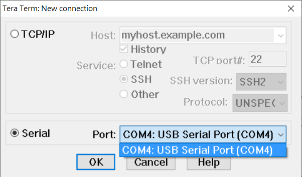
Installed Tera Term(or Putty) on your computer. To open a terminal, you will need to know the COM port for the board.
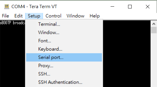
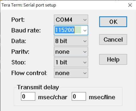
Setup -> Serial Port
Full terminal Settings:
• baud rate: 115200 bps
• data bit: 8
• no parity
• stop bit: 1
Login by enter root
Password : root
Before Running the application , you should copy DNNDK Tools and Application to the Evaluation Board
The steps below illustrate how to setup DNNDK running environment for DNNDK package is stored on a Windows system. Download and install MobaXterm on Windows system. MobaXterm is a terminal for Windows, and is available online at https://mobaxterm.mobatek.net/.
Setup the address IP on the Board in the tera term, enter below
$ifconfig eth0 192.168.0.10
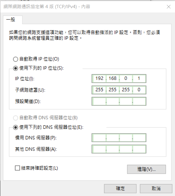
Assign your laptop/PC a static IP address
- Double click on the network interface to open it, and click on Properties
- Select Internet Protocol Version 4 (TCP/IPv4) and click Properties
- Set the Ip address to 192.168.0.1 (or any other address in the same range as the board)
- Set the subnet mask to 255.255.255.0 and click OK
Launch MobaXterm and click Start local terminal
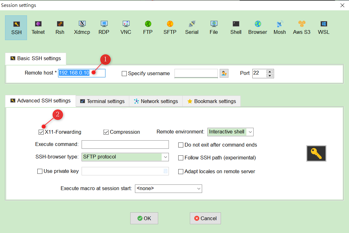
- Click New Session
- Enter 192.168.0.10 in the Remote Host
- Make sure X11-Forwarding is Checked
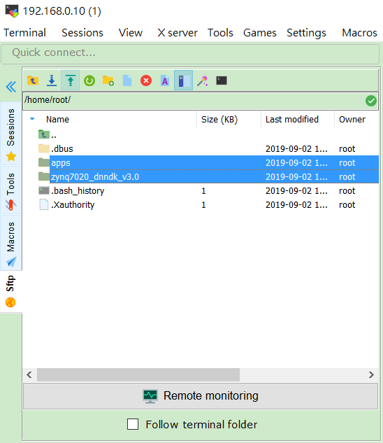
- Copying DNNDK Tools and Application to the PYNQ-Z2 Board
-
Install DNNDK into PYNQ-Z2 board
- Execute the sudo ./install.sh command under the zynq7020_dnndk_v3.0 folder
$./zynq7020_dnndk_v3.0/install.sh- Check the DPU of the board.
$dexplorer -w- Check the version information of DNNDK
$dexplorer -v -
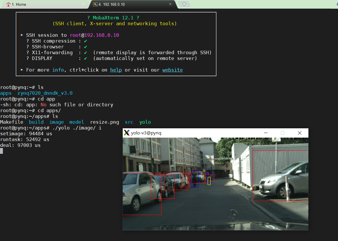
Run the yolov3 applications
- Change to the directory into
apps folderand run make
$cd <PROJ ROOT>/apps $make- After running make,generate the complier file under the foloder
Launch it with the command
./yolo ./image i - Change to the directory into
