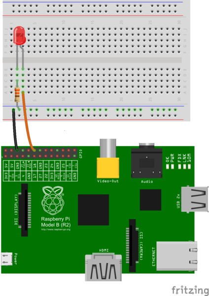
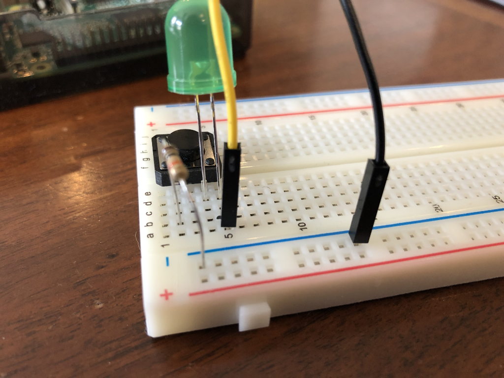
The RPi library allows two modes. The code in this repository prefers the BOARD numbering for simplicity of learning and compatiblity across multiple versions of Raspberry Pi hardware.
GPIO.setmode(GPIO.BOARD)
- Pin 6 (ground) on pi to negative channel on breadboard
- Jumper from negative to row 23
- button straddles row 23 and 25
- row 25 to pin 16 on pi
- Pin 8 on pi to row 5 on breadboard
- Resistor from negative to row 4
- LED from row 4 (-) to row 5 (+) (positive=long)
- Pin 10 on pi to row 10 on breadboard
- Resistor from negative to row 9
- LED from row 9 (-) to row 10 (+) (positive=long)
- Pin 12 on pi to row 15 on breadboard
- Resistor from negative to row 14
- LED from row 14 (-) to row 15 (+) (positive=long)

