The purpose of building a very simple self-driving car in the form of a robot is to create a practical project. It is possible to add better capabilities and considerations in controlling the robot, as well as its features.
This robot is intended to be an extremely simple self-driving car. Therefore, we consider two lines drawn with a wire as the environment of a street, where the robot is supposed to keep itself in the middle of these two lines and not deviate.
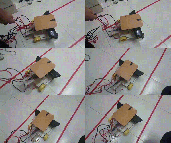
In this project, as expected and shown in the accompanying video, there is a robot with four wheels. We have used four 12V DC motors (although it could have been done with two motors and two axles, which would have allowed us to utilize sensors in the wheels and achieve higher precision). Furthermore, we have utilized a structure as the robot's body, which was designed and fabricated using software. Additionally, we have used a 360 XBOX Kinect as a camera and a distance sensor. The reason for choosing this equipment is its ability to provide stereo vision, as it has two cameras that can measure distance accurately. Of course, this device has many capabilities that can be utilized. It is beyond the scope of this discussion, and one can search for it on the internet. Additionally, the Arduino Nano has been used as the robot controller.
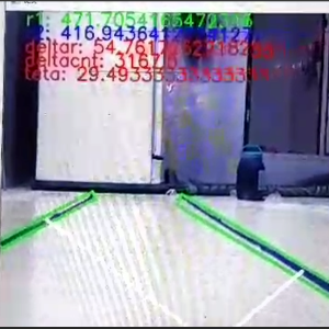
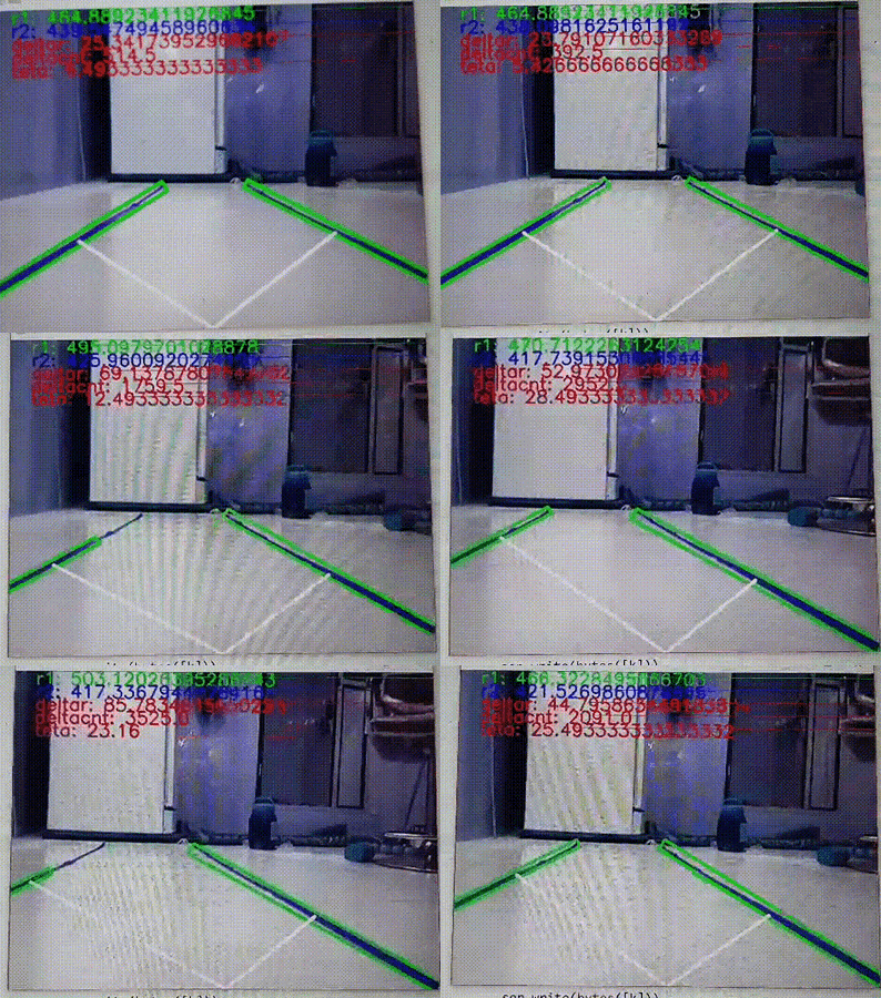
As shown in the figure below, this robot is designed to measure the distance between two lines and subtract them from each other as feedback for the desired objective, which is to stay between the lines while maintaining a consistent distance from both sides.
This difference was measured through image processing, and since it is a heavy task that cannot be performed by Arduino, it was done using a computer. The information (delta r) is sent to Arduino through serial communication between the computer and Arduino. In the top figure, r1 represents the distance of the robot from the left side, r2 represents the distance of the robot from the right side, and teta is the rotational angle that needs to be corrected. In Arduino, commands are given to the motor, specifying the time and amount of rotation.
This project consists of two codes. The first code, written in the Python programming language, handles control tasks, image processing, and serial communication. The second code is related to Arduino and is written in C++.


