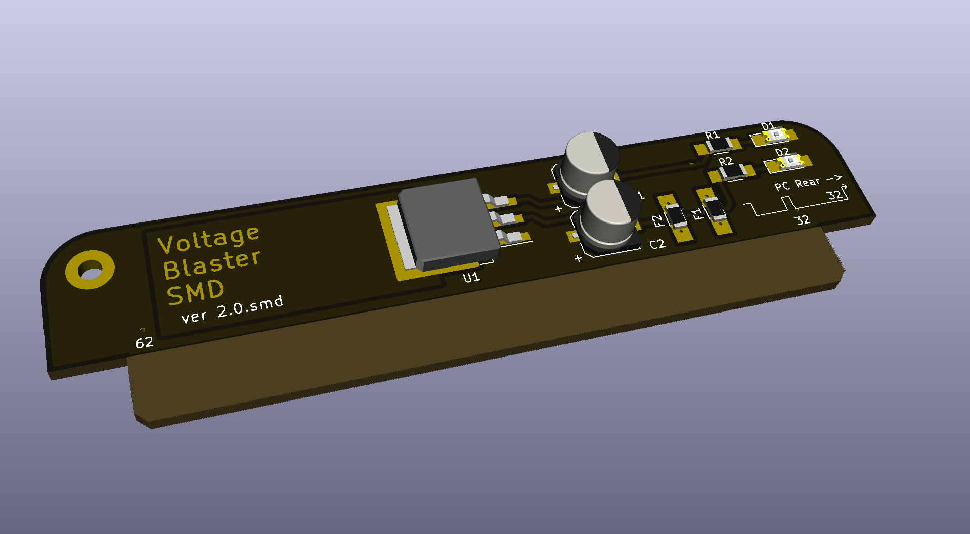
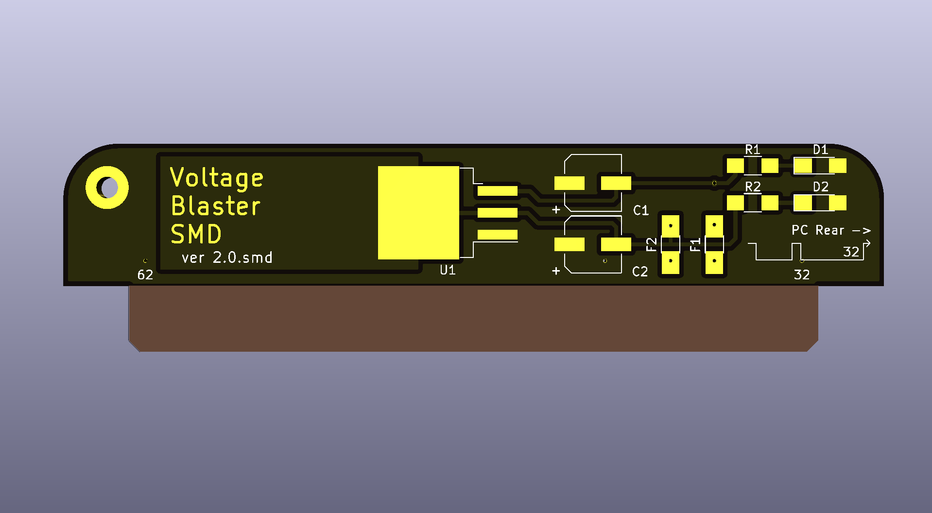
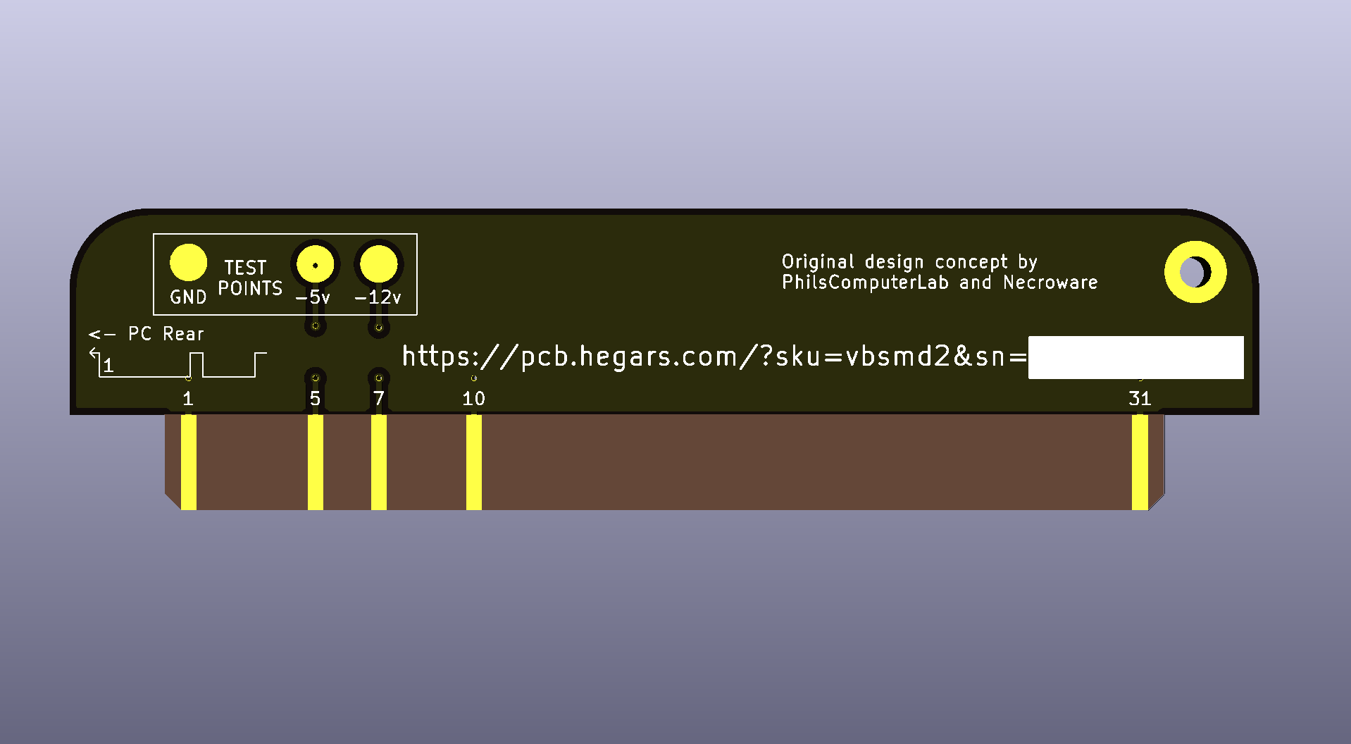
Voltage Blaster Mod
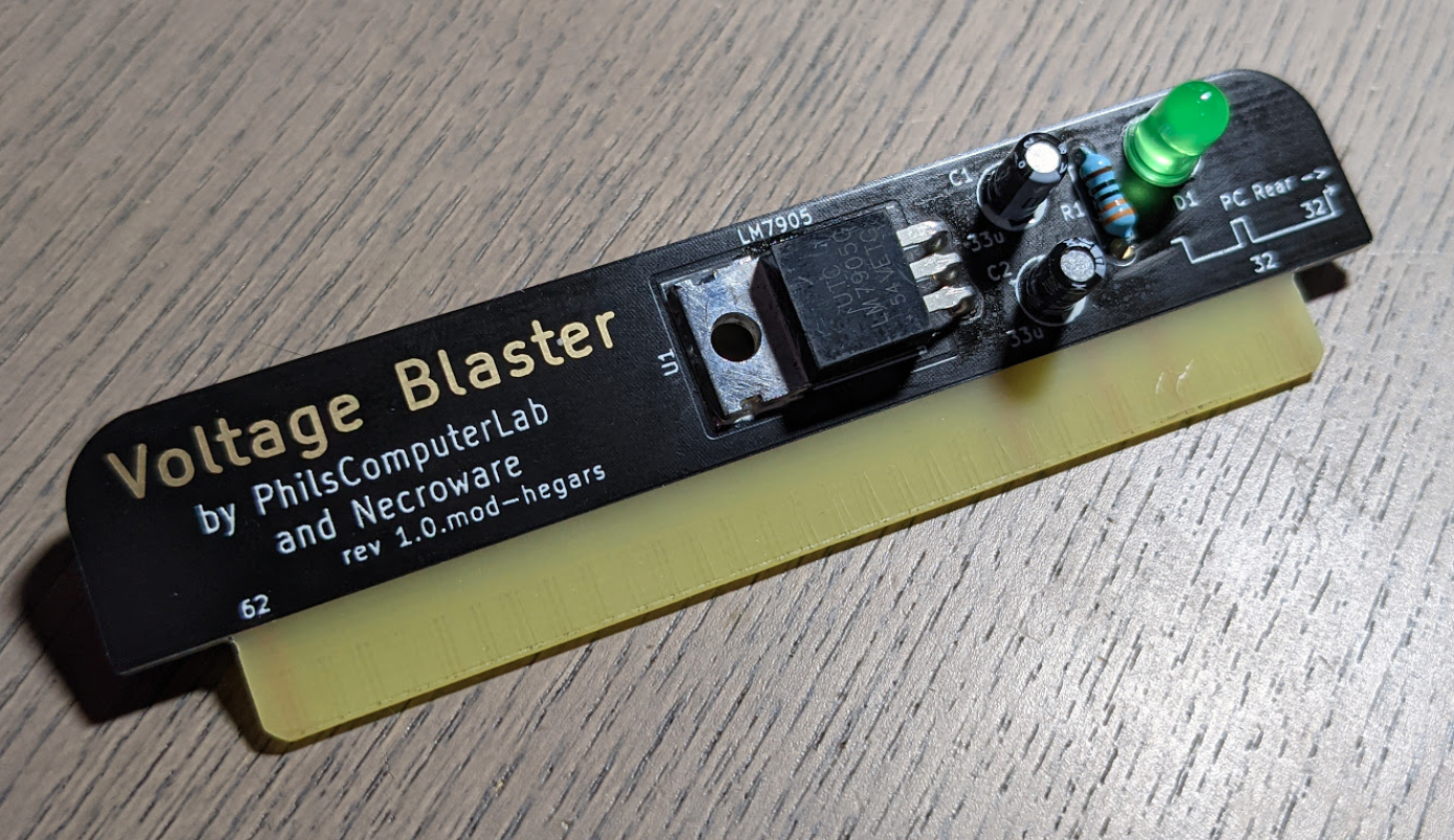
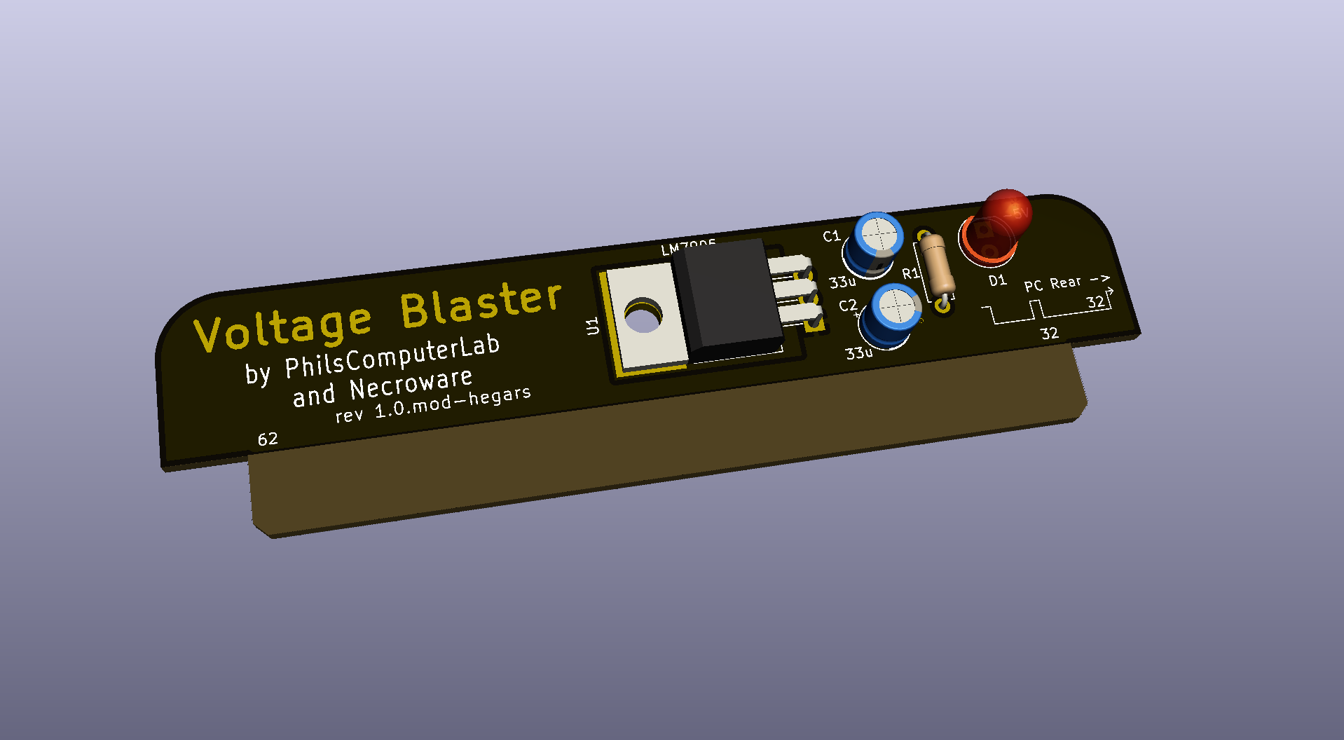
Voltage Blaster is a very simple circuit, which provides -5V through ISA slot for systems with power supply which don't provide such voltage. It was originaly created in cooperation between PhilsComputerLab and Necroware then forked and modified by Hegars.
Changes From Necroware version
PCB
- Updated - Pulled Mask from ISA Cconnector
- Updated - Pulled Mask from the top of TO-220 package to allow soldering
- Added - Linked copper zone beneath TO-220 package to -12v for soldering
- Updated - NPTH mount on TO-220 package changed to PTH
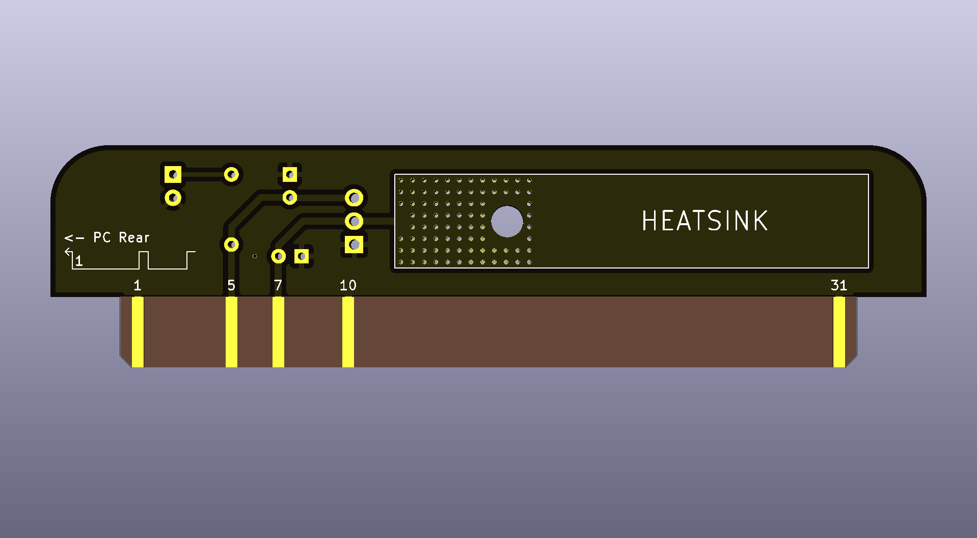
- Added - Added Vias under TO-220 for heat transfer to rear copper zone
- Added - Added Copper zone on rear for heat sinking and capacitance (Linked at -12v)
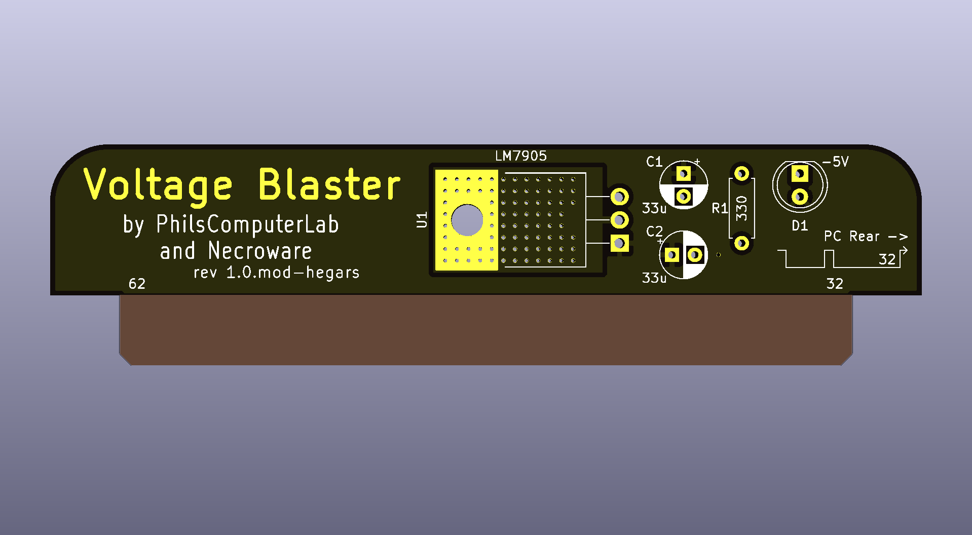
- Updated - Slight components aliginments
- Moved - Logo changed from Silk to Mask and moved credits around
- Updated - Version number
- Updated - PCB corners rounded
- Updated - "PC Rear" locator to make it a bit more clear the direction
- Added - Pin numbers added for relevent pins for refernece
- Removed - Unused Pins on ISA Connector
SCH
- Updated - Changed to global lables
- Updated - Version number
Many thanks to Necroware and PhilsComputerLab, I owe you some beers..
Voltage Blaster SMD
In Version 2 I have moved all components to SMD variants
SMD Changelog
- Added - SMD version with TO-263-3 package (LM2990S-5.0/NOPB LCSC-C201697)
- Updated - Componets to SMD variants
- Added - PTC Fuses on both power rails
- Added - Mounting hole for reasons
- Added - Test Points on rear for science
- Added - LED for -12v rail
- Moved - Logo and credits to rear
- Updated - Verison numbers
- Add? - Minimum load resistor?
SMD BOM
| Reference | # | LCSC | Description |
|---|---|---|---|
| U1 | 1 | C201697 | linear voltage regulator |
| C1,C2 | 2 | C88824 | electrolytic capacitor 33µF |
| F1 | 1 | C692148 | fuse |
| F2 | 1 | C692149 | fuse |
| D1 | 1 | C192678 | light emitting diode |
| D2 | 1 | C192674 | light emitting diode |
| R1,R2 | 1 | C269588 | resistor |
Original Voltage Blaster Description
Why do I need this?
Back in the days of XT and AT compatible computers the standard power supply had to provide 5V, 12V, -12V and -5V. A lot of hardware, especially sound cards, needed -5V to work properly. This voltage was provided for the ISA expansion cards on the pin B5. As time passed, AT systems and compatible power supplies were replaced by ATX. In the beginning they also provided -5V, but then less and less expansion cards needed such voltage and as soon as ISA was considered obsolete, ATX standard eventually dropped -5V rail requirement. Today it is not possible to buy a new AT power supply, but ATX power supplies can be used through an adapter. However, since almost none of the modern ATX power supplies will provide -5V, you could run into problems, when trying to use an old ISA expansion card, which needs this voltage. Famous examples are Creative Sound Blaster 2.0, Pro Audio Spectrum sound cards and many others. This is where the Voltage Blaster comes into play.
How does it work?
All voltage pins in the ISA slots are directly connected to each other and to the PSU. When using a PSU without -5V support, the ISA slot pin B5 is just floating. The idea behind the Voltage Blaster is very simple. What if one of the ISA expansion cards will provide -5V and feed it through the ISA slot in reverse. Well since the ISA slot pin B7 provides -12V, it's just a matter of using a linear voltage regulator LM7905 and connect its output to the pin B5 of the ISA slot.
Bill of materials
| Reference | # | LCSC | Description |
|---|---|---|---|
| U1 | 1 | C427634 | linear voltage regulator LM7905 |
| C1,C2 | 2 | C3314 | electrolytic capacitor 33µF |
| D1 | 1 | C99697 | light emitting diode (optional) |
| R1 | 1 | C58608 | resistor 330 Ohm (optional) |
Parts D1 and R1 are optional and are only required if you want that the diode is lighting, when -5V are generated.
