MyEko is composed of several PCBs and this test will make use of 2 of them:
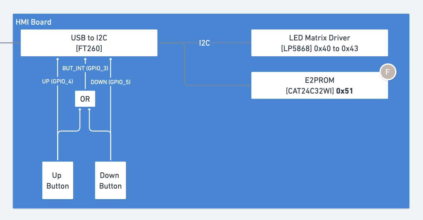
- the HMI board, with a LED matrix (controlled over i2c) and 2 buttons (via GPIO)
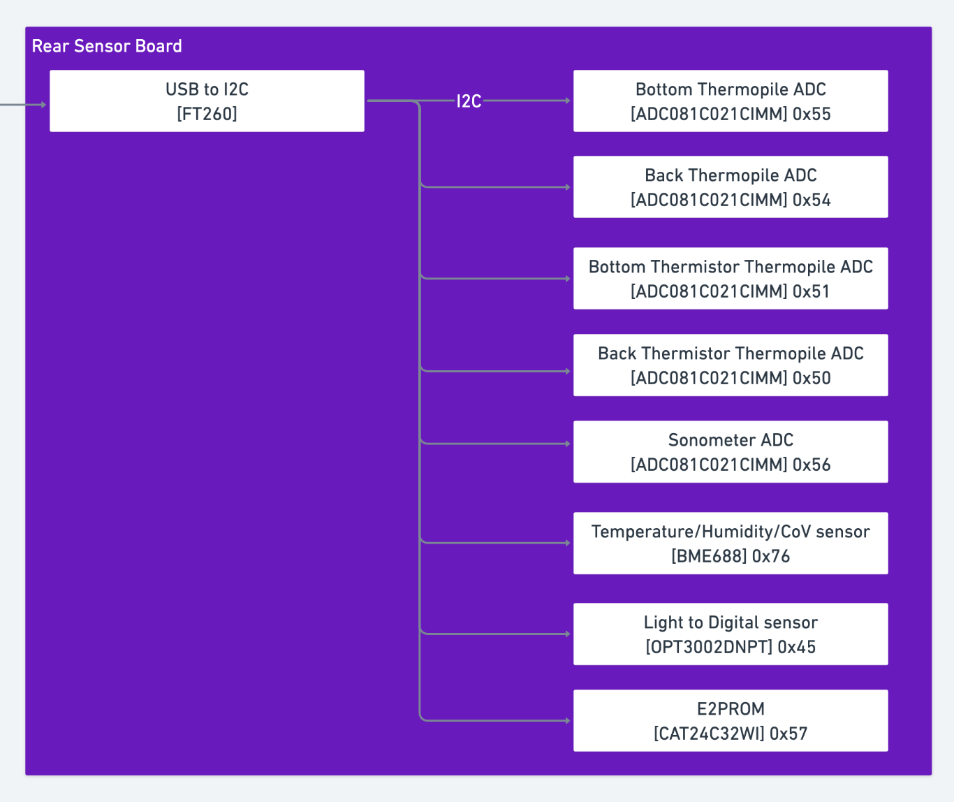
- the rear sensor board, with a number of sensors like thermistors, thermopiles, air temperature and humidity, etc. All those sensors are avilable over i2c.
Both boards use an i2c-usb bridge to communicate with the host computer, using a FT260 chip.
You can use the programming language of your choice, but you should provide instructions to build and/or run your code.
You can treat the objectives in the order you prefer.
You have full access to the internet and you are encouraged to use it.
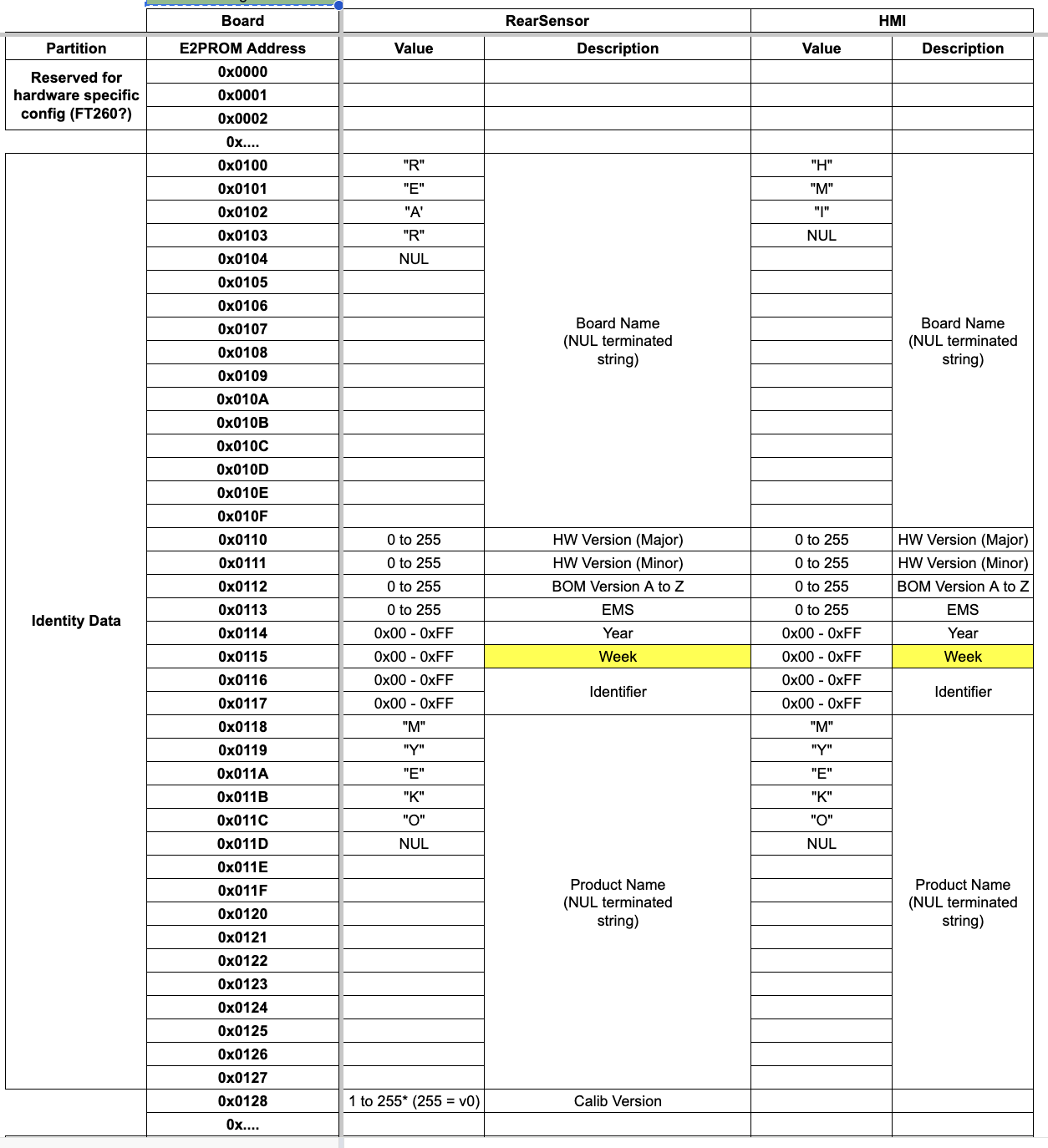
Read and display the board info from the EEPROM of both boards.
The EEPROM model number, i2c address as well as the eeprom data layout are provided in the resources section.
Implement a simple application that reacts to button presses on the HMI board.
You can ignore the interrupt and simply poll the 2 GPIOs.
You will have to configure the FT260 to enable GPIO 4 and 5 by turning off the uart_dcd_ri functionality with echo 0 > /sys/bus/hid/drivers/ft260/<ft260-hmi>/uart_dcd_ri.
Note: using the led driver of the HMI is not trivial and out of scope for this test.
Implement a simple application that reads the temperature from the Back Thermistor of the rear sensor board.
The i2c address and model number of the thermistance ADC are provided in the resources section. To read and convert the ADC tension into a temperature, please refer to the RearSensorBoard.pdf document in the doc folder.
You can use the default values for the thermistor parameters (provided in the document), you don't have to go read the calibration values in the EEPROM.
There is a kernel driver for the FT260: https://github.com/MichaelZaidman/hid-ft260
An older version is available in the kernel, but you should use the one from the link above instead.
This driver will create an i2c bus /dev/i2c-xxx and a gpiochip /dev/gpiochipXXX for each FT260.
This graph shows the components of the HMI board and their i2c addresses:
This graph shows the components of the rear sensor board and their i2c addresses:
This table shows the EEPROM layout of both boards:
Note: MSB to LSB for all registers (BIG ENDIAN). Max adressing is 0x0FFF.


