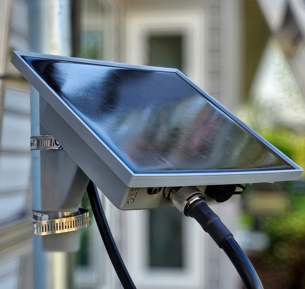
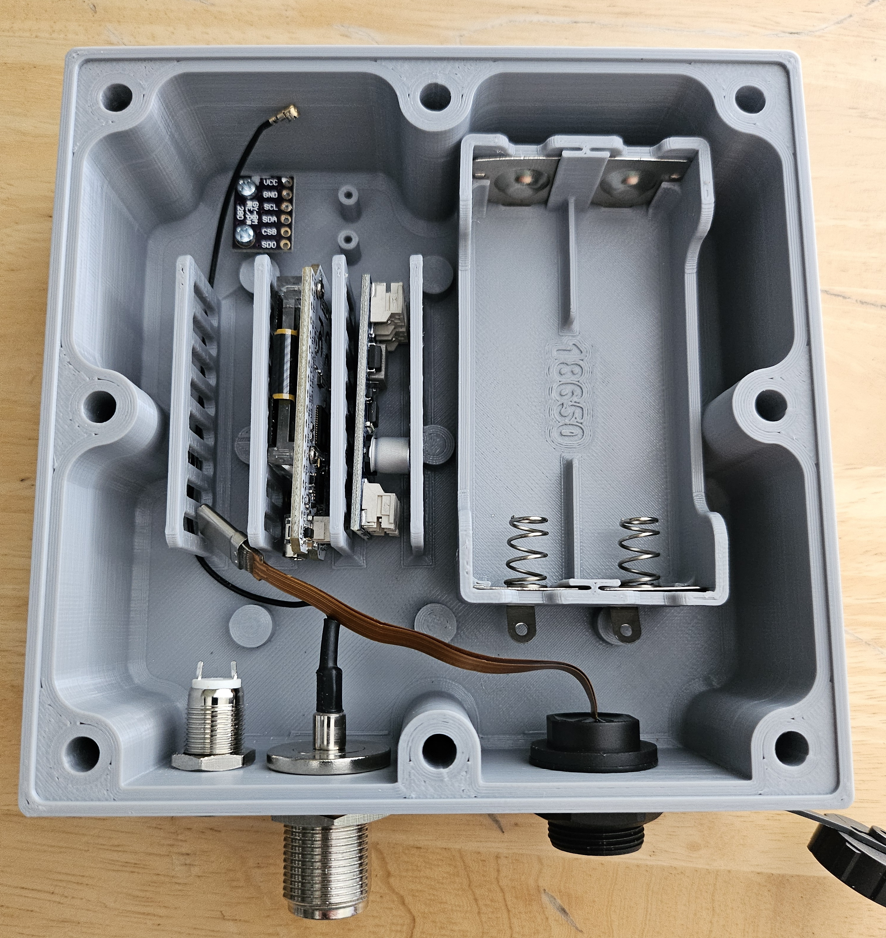
This is a "universal" enclosure. The PCB Cage in the enclosure accommodates the RAK 19007 Starter Kit, Heltec WiFi LoRa32(V3), Heltec T114, or any other similar board sizes less than 60mm x 35mm x 11mm thick
The design features the option for N-Type or SMA connectors, and an optional waterproof USB-C pass-though. An inexpensive MPPT controller makes solar charging more efficient.
| Qty | Description | Links |
|---|---|---|
| 1 | 6V 4.5W Solar Panel 165mm x 165mm | https://www.amazon.com/dp/B0D3QGXL7R https://www.aliexpress.us/item/2251832715035737.html |
| 1 | CN3791 6V MPPT Solar Charger circuit board | https://www.amazon.com/Controller-Charger-Battery-Charging-Conversion/dp/B0CLPGG79Z https://www.aliexpress.us/item/3256806488461808.html |
| 2 | 18650 Li-ion battery high quality | https://store.rokland.com/products/sanyo-ncr18650ga-3450mah-10a-battery-lilygo-ttgo-meshtastic-t-beam https://www.18650batterystore.com/products/panasonic-ncr18650ga-ga6 |
| 1 | Dual 18650 battery holder (wire in parallel) | https://www.amazon.com/gp/product/B09V1LWPCD or print your own (see provided 3D printer files) using https://www.aliexpress.us/item/2251832632615852.html |
| 1 | 10mm waterproof latching push button power switch | https://www.amazon.com/dp/B07MQ86LYD https://www.aliexpress.us/item/3256805159449536.html |
| 1 | USB C waterproof Female to Female panel pass-thru 16mm diameter 0.2 meter length (optional, see notes) | https://www.aliexpress.us/item/3256806032665821.html |
| 1 | Thread-type Waterproof Connector Dust Cover | https://www.aliexpress.us/item/3256805936943547.html |
| 1 | IPEX female to N-type bulkhead mount female connector 16mm and/or if you need SMA, IPEX female to SMA bulkhead mount female connector 16mm |
https://www.amazon.com/POBADY-Coaxial-Pigtail-Wireless-Repeater/dp/B0C8M9NR3R https://www.amazon.com/gp/product/B0C8LVSH88 |
| 2 | 6 inch zip ties for fastening battery | |
| 9 | M3 x 5.7mm heat-set threaded inserts | |
| 6 | M3 x 10mm socket cap screws for attaching mount to electronics enclosure | |
| 8 | M5 x 4mm heat-set threaded inserts | |
| 8 | M5 x 30mm socket cap screws for attaching electronics enclosure to solar panel | |
| 1 set | M8 x 70mm or 5/16" x 3" hex bolt, and matching washer and lock nut (if using hinge option) | |
| 1 | Silicone Foam Strip | https://www.amazon.com/dp/B0CBR7H2PG |
| 1 | Small tube 100% Silicone Sealant | |
| 2 | Stainless steel hose clamp sufficient for your antenna mast diameter | |
| 1 | 9/16 inch O-Ring for Body Plug (if using optional plug) |
- If you use a LiPo battery pack instead of the 18650s, be sure the wiring polarity is correct on the LiPo pack before inserting into the MPPT controller. Unfortunately, there is no standard for LiPo battery pin polarity and different manufacturers use different wiring polarity for the same connector. Reversed polarity usually has undesirable results.
- If you change the solar cell or MPPT controller, you must be sure they are matched. A 6V solar cell must use a 6V MPPT controller, a 9V cell with a 9V controller, etc.
- The USB-C pass-through connector is intended for updating firmware if using a Heltec or other radio that does not support OTA firmware updates. The RAK 19007 and other radios that support BT updating do not require the USB-C pass-through. In which case the 16mm opening can be used to insert a IPEX to SMA bulkhead connector (see parts list) for adding a external BT (WiFi) SMA antenna. If you simply wish to seal the hole, a 3D-Printed hole plug is provided.
- 3D printing:
- All 3D printing files for this project are maintained at https://www.printables.com/model/1012624-w9etc-meshtastic-solar-node
- You only need one of the pole mounts. One is a simple mount which attaches the solar panel parallel to a pole. The other is hinged mount that allows the solar panel to be positioned at an angle to the pole.
- Print the electronics enclosure component using PETG, 20% infill, & 5 perimeters for better water resistance
- Supports are required for the simple pole mount
- Print the hinged mount L-channel facing down. Supports are needed for the notches in the L-channel and the slot for the hose clamp/zip tie.
- Supports are recommended for the holes in the enclosure
- Be sure to flip the solar cell frame back so the solar panel side is facing up for printing. It does not need supports.
- Assemble in an air conditioned or low humidity space to prevent condensate from forming inside the electronics enclosure once sealed.
- The set of four standoffs next to the electronics enclosure PCB cage fit the RAK19004 Green Power Module in case you want to use it. The MPPT module listed in the part above is a far better choice. The standoffs also fit a 3.3v BME280 Temp/Hum sensor.
- All epoxy coated solar panels (most of them) will yellow severely in the sun. Spraying them with automotive clear coat will prevent this. Small cans of clear coat are available at your auto parts store.
Install all the heat-set threaded inserts. There are many internet videos showing how to use heat-set inserts. Ensure a screw is perfectly straight and when threaded into the insert. A heat-set insert can be re-heated to correct an incorrect installation.
If the solar cell contacts are blocked by the rear solar cell frame back, relocate the solar cell contacts by scratching off the PCB insulation and taping over the original contacts.
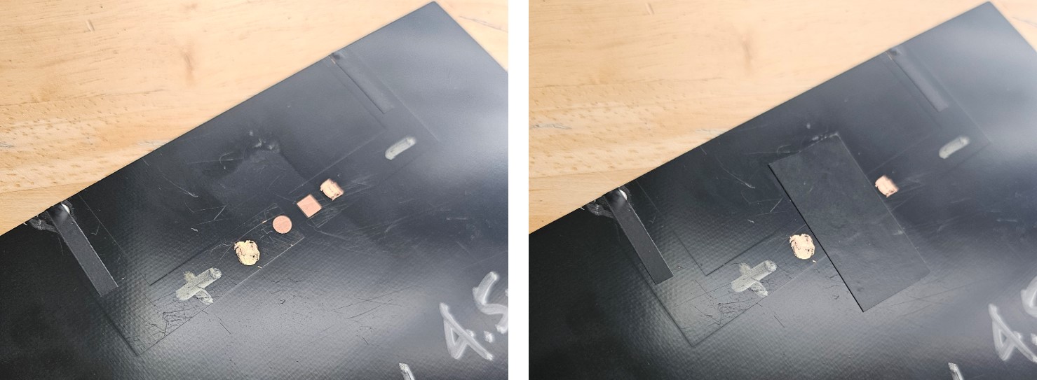
Insert the Silicone Seal Strip into the channel around the solar cell frame back (the side facing the electronics enclosure). The 3mm diameter foam strip will seem too large at first, but the cavity behind the groove is 3mm and will accommodate the strip. Use a round headed spudger to compress the foam strip onto one side of the channel while applying downward force.
![]()
Apply silicone sealant generously on the rear solar cell frame filling the channel on side facing the solar cell. Then combine the front solar cell frame, solar cell and rear frame into one assembly. Ensure the rear frame fully snaps into the front frame securely sandwiching the solar cell.
![]()
Install Antenna connector, USB-C connector (or plug), power switch.
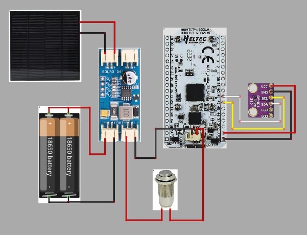
The electronics wiring diagram for a Heltec Lora32 V3 with a BME280 environmental sensor is shown below. Note the CN3791 6V MPPT Solar Charger circuit board output is directly connected to the battery input of the radio through the switch.
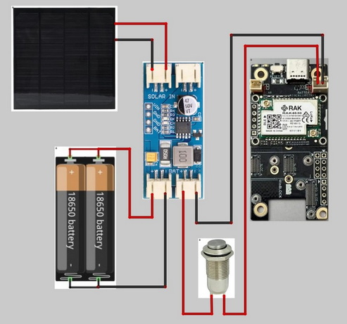
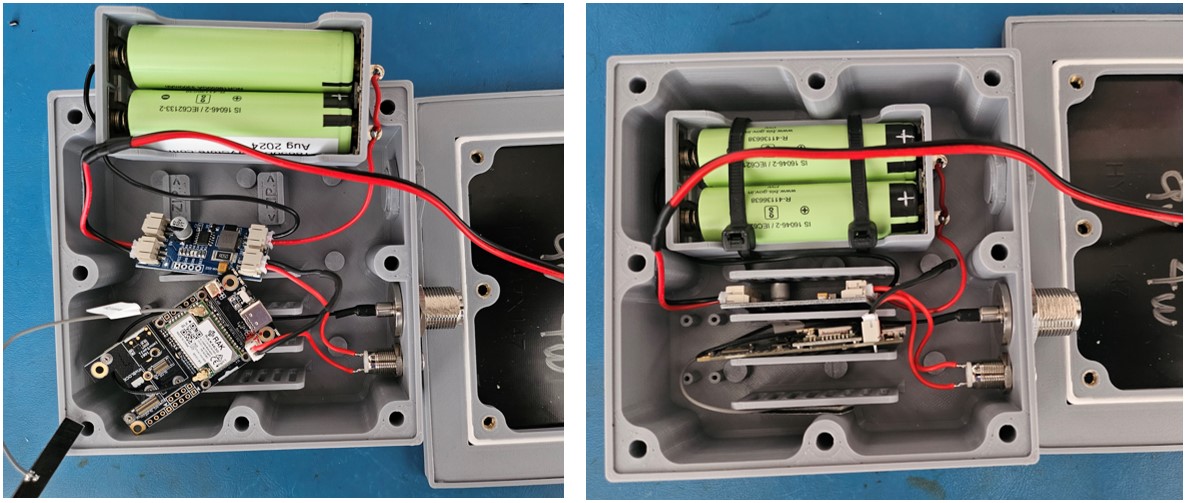
The electronics wiring diagram for a RAK19007 Starter Kit is shown below. Note the CN3791 6V MPPT Solar Charger circuit board output is directly connected to the battery input of the radio through the switch. Do not connect the MPPT board output to a solar input of the radio board.
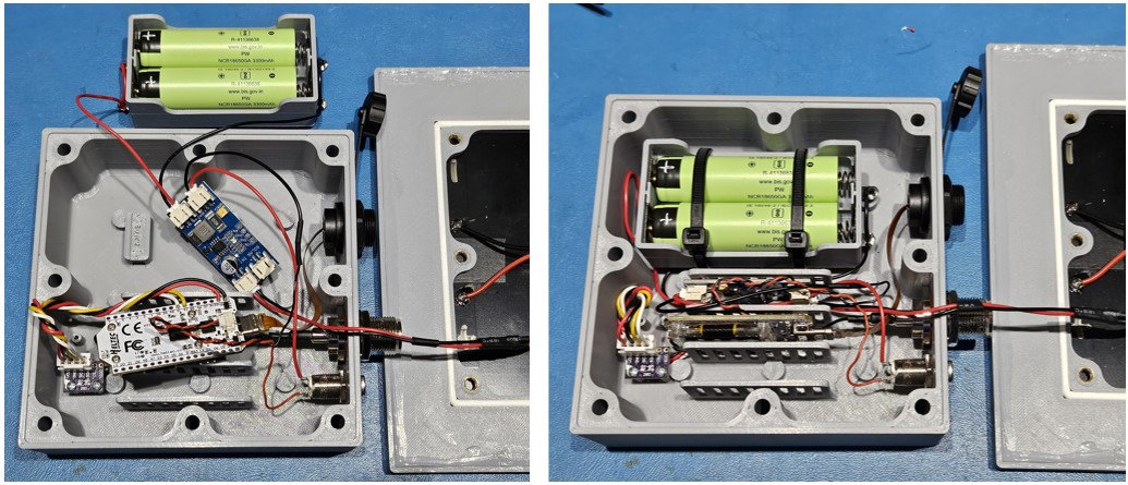
Perform a trial placement of circuit boards to determine a wiring plan and wire lengths. Photo shown below has a Heltec Lora32(V3), CN3791 Solar MPPT controller, BME280 Environmental Sensor, USB C waterproof Female to Female panel pass-thru, IPEX female to N bulkhead mount female connector, latching push button power switch, and 3D printed dual 18650 battery holder.
Heltec Lora32(V3) assembly wired prior to final placement of components & final placement prior to closure
RAK19007 assembly wired prior to final placement of components & final placement prior to closure
Using the M5 x 10mm socket cap screws, attach the solar panel assembly to the electronics enclosure. Do not exceed the specified 10mm length of these screws. Be sure there are no wires pinched between. A waterproof seal is achieved when the electronics enclosure is pressed into the silicone foam strip, so be sure the M5 screws are firmly and evenly seated.
The pole mounts are attached to the electronics enclosure using M3 x 10mm screws. Do not exceed the specified 10mm length for these screws. The symmetric screw pattern allows a variety of mounting offsets.
