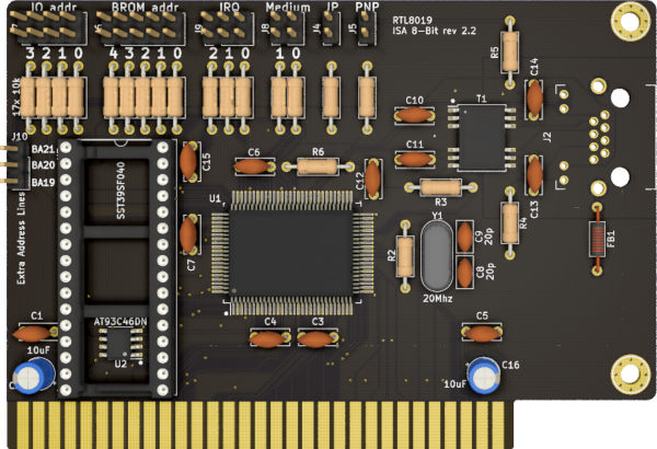
This is an 8bit reimplementation and repackaging of Manawyrm's ISA8019, a NE2000-compatible card for the ISA bus.
Differences from the original version include:
- 8bit only design (significantly more compact than the 16bit version)
- Most of the components are now THT (except EEPROM, Network IC and transformer)
I take NO responsibility for what happens if you decide to build and use this card. Your computer might crash, catch fire or be destroyed in other nasty ways. Also, as this card is mostly based on the work of others, You're encourauged to take what you deem fit from this, and use it in your projects!
Additionally, do NOT CONTACT Manawyrm FOR SUPPORT, while this board is derived from their work, it is not their product, please do not waste their time.
The board can work in 3 modes:
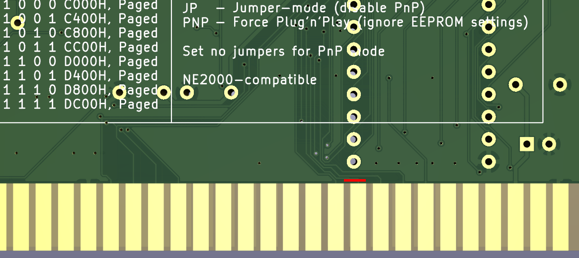
- Jumper mode (JP jumper set) This mode allows for manual configuration of any parameters (I/O address, IRQ, BROM address & size, etc.) manually via jumpers. Refer to the back of the PCB for details.
- EEPROM mode (also called "Jumperless", no jumpers set) In this mode, all parameters can be configured via the RSET8019.EXE dos utility and will be stored in the 9364 I²C EEPROM.
- PnP mode For modern computers and operating systems like Windows 9x or Linux, this mode is ideal. Resource management will be done by the BIOS or OS.
I use this 8bit variant in Jumper mode (hard to find an 8bit machine with PnP support...).
- RSET8019.EXE for DOS, can set EEPROM parameters, also includes diagnostic functions
- pg8019 for DOS, can initialize EEPROM, set MAC address, vendor/product IDs
Revisions 2.4 onward support SRAM chips (e.g. AS6C4008) on the boot ROM slot by correctly bridging J11.
J11 setting, ISA edge connector looking DOWN
EPROM
    | .
    | |
    . |

SRAM
    . |
    | |
    | .
This is not yet tested by me, but is reported working by modifying a previous revision. Reference this issue.
If you wish to use a SRAM chip for UMB support in previous revisions, cut the traces that go to pin 29 and 31 of the boot ROM, and invert them (connect the trace that went to 29 to pin 31, and vice-versa).
The RTL2UMB software can be found in this thread.
You can use LCSC to source most of the ICs.
- U1: RTL8019AS
- U2: AT93C46DN
- T1: 13F-39MNL
- J2: C133529 CKMTW
- Y1: 20Mhz HC49 crystal
- C9, C9: 20pF ceramic capacitor
- C1,C3-7,C12,C15: 100nF ceramic capacitors
- C2, C16: 10uF/25v electrolytic or ceramic capacitors
- C10-14: 1nF ceramic capacitors
- R4,R5: 1k resistors
- R6-22: 10k resistors
- R3: 200ohm resistor
- R2: 1M resistor
- FB1: Ferrite bead
- ISA bracket: Keystone 9202-1, plus screws. This bracket is made for ISA modems, the hole will be slightly wider than an RJ45 socket.
- Revision 2.3 has only minor changes, but has not yet been tested by me. Reports are welcome.
- I received a report of this board not allowing Sergey's Micro8088 to boot unless the IRQ6 line is cut on the network card. I have not been to reproduce this (maybe because I'm using a terminated backplane?), as the builds I completed are working fine on my Micro8088 cards, but be aware in case you incur in the same issue. Revision 2.3 keeps IRQ lines 6 and 7, but makes them jumperable and by default disconnected, so if you have that revision, this should no longer be an issue.
The picture above shows where to cut to isolate IRQ6 in case you suffer the described issue. The trace is located on the backside of the PCB.
- Thanks to Manawyrm for the original project

